1 Introduction
Piezoelectric materials have been developed for more than 140 years since 1880. The existence of piezoelectric effect provides a variety of scenarios for piezoelectric material applications. The use of piezoelectric materials for the preparation of microelectromechanical devices, the development of miniature resonators [1, 2], sensors [3, 4] and micro-energy-supply chips [5-7], and transducers [8] have been realized. Commonly used piezoelectric materials can be broadly categorized into two types, ceramics with very high electromechanical coupling coefficients, and polymers that can compensate for their lower piezoelectric properties with their high machinability. Piezoelectric polymers have more significant bending and tensile properties compared to piezoelectric ceramic materials. Piezoelectric polymer materials are dominated by carbon chains and are more flexible than single crystals and ceramics [9]. This high flexibility allows them to withstand greater strains, making them more suitable for application scenarios with large bending and twisting requirements, especially in sensing applications. Flexible sensors with good flexibility, ductility can flexibly change their morphological structure according to the demands of the detection environment. Therefore, it can be adapted to complex and diverse non-smooth surfaces, the application range of the sensor is nearly expanded. With the rapid development of wearable devices, the good flexibility and excellent biocompatibility of piezoelectric polymers fulfill the requirements for wearable electronic components. Polymers with piezoelectric properties are nylon-11 [10], poly(lactic acid) (PLLA) [11], poly(lactic-co-glycolic acid) [12] and poly(vinylidene fluoride) (PVDF) [13]. PVDF, poly(vinylidene fluoride)-trifluoroethylene (PVDF-TrFE), poly(lactic acid) (PLA) and polyamide (PA) have been widely used in pressure sensors, shock sensors, audio sensors, chemical sensors, ultrasonic sensors and medical sensors.
PVDF has a high piezoelectric coefficient among the known piezoelectric polymers and it has excellent chemical stability and flexibility [14]. However, at present, improving the piezoelectric properties of piezoelectric polymers in practical applications is still a challenging task due to their own low piezoelectric strain constant (dij) and conversion efficiency. In order to make piezoelectric materials better meet the modern development trend, researchers have carried out research and validation work on graft modification of piezoelectric polymers, composite of piezoelectric ceramics and polymers through different processes, and structural design.
The preparation of composites using PVDF as a matrix with the introduction of suitable fillers is a simple and effective way to increase the content of polar phases in PVDF. In the present study, the types of fillers added can be broadly categorized into two groups, one is piezoelectric ceramics with high piezoelectric coefficient [15, 16], such as lead zirconate titanate (PZT), barium titanate (BaTiO3). This type of fillers can mainly compensate for the polymer through the piezoelectric coefficient of the ceramic material itself, but a high proportion of piezoceramics can result in a large number of holes and cracks. Another type is conductive fillers such as Ag, graphene and carbon nanotubes [17-19], and the conductive fillers can not only improve the current transmission ability, but also have good compatibility with polymers. In addition, combining the advantages of multiple fillers [20, 21] to form diversified composites can also further improve the piezoelectric performance of PVDF-based piezoelectric devices.
Piezoelectric materials have always been one-dimensional (1D) or two-dimensional (2D) structures due to limitations in design and fabrication. With the development of 3D printing technology and the good plasticity of PVDF itself, more and more researchers have started to apply 3D printing technology to the preparation of PVDF and related devices. The use of 3D printing for the preparation of PVDF devices enables the customization of PVDF devices with complex geometries while increasing their β-phase content. Currently published results have used direct ink writing (DIW), fused deposition molding (FDM), and stereo lithography apparatus (SLA) for printing PVDF piezoelectric devices [22-25]. Among them, DIW has many advantages, including a simple process, fast processing speed, and high compatibility with printing materials. It can easily achieve multi-material integration. The traditional preparation methods of PVDF piezoelectric films need to be electropolarized under high pressure to have macroscopic piezoelectric properties. However, high-voltage polarization is prone to energy loss and film breakdown damage. PVDF piezoelectric films prepared by direct-write 3D printing technology can not only realize the non-polarized preparation process, but also carry out the patterned deposition of the film, to better meet the increasingly diversified and personalized market demand.
In this paper, PZT was selected as the filler, and PVDF binary composite piezoelectric films were prepared by DIW, and the effects of filler content on the β phase content, crystallinity and electrical properties of the composite films were systematically investigated.
2 Experimental procedure
2.1 Materials
The raw materials for the experiments include polyvinylidene fluoride (PVDF, Solvay, USA), lead zirconate titanate (PZT, pre-fired powder, Zibo Yuhai Electronic Ceramic Co., Ltd.), dopamine hydrochloride (DA·HCl, 99%, Shanghai Aladdin Biochemical Technology Co., Ltd.), tris(hydroxymethyl)aminomethane (≥99.8%, Shanghai Aladdin Biochemical Technology Co., Ltd.), dimethyl sulfoxide (DMSO, 99%, Shanghai Macklin Biochemical Co., Ltd.), acetone (ACE, 99.5%, Sinopharm Chemical Reagent Co., Ltd.).
2.2 Surface modification of filler particles
Tris(hydroxymethyl)aminomethane was dissolved in 400 mL of deionized water to formulate a 10 mmol/L Tris buffer with a pH of 8.5. 2 g of PZT was added to the buffer and sonicated for 30 min, and 1.2 g of DA·HCl was added and magnetically stirred at 50 ℃ for 8 h to obtain PZT@PDA. The PZT@PDA was washed with deionized water and dried in an oven at 60 °C for 12 h.
2.3 Preparation of PVDF composite films
DMSO and ACE were weighed and mixed homogeneously, and the corresponding filler was weighed into the mixed solvent according to the ratios shown in Table 1. The mixed solution was put into an ultrasonic cleaner and ultrasonicated for 1 h to promote the dispersion of the filler. The PVDF powder was slowly added and ultrasonicated for 1 h, and then magnetically stirred for 3 h to promote further dissolution of the PVDF powder. After static defoaming to obtain a uniform texture of the PVDF binary composite solution.
| Sample | w(PZT)/% | w(PZT@PDA)/% |
|---|---|---|
| PZT-0 | — | — |
| PZT-1 | 1 | — |
| PZT@PDA-1 | — | 1 |
| PZT@PDA-3 | — | 3 |
| PZT@PDA-5 | — | 5 |
The PVDF solution was transferred into a 10 mL syringe that was mounted on a 3D printer (HYREL 3D, USA) for DIW. These steps include designing and slicing stereolithography (STL) model, and printing. The experiments were performed using Prusa slicer software for slicing and setting parameters such as print path, print speed, layer height, extrusion width, and fill ratio. When the slice fill ratio was set to 100%, a dense film was printed; and when it was set to 20%, a single line was printed. The PVDF film obtained from printing was placed in a drying oven and dried firstly at 40 ℃ for 12 h and then at 60 ℃ for 24 h to get rid of the solvent, and a film of uniform thickness was made [26].
2.4 Characterization
Field emission scanning electron microscope (SEM, Nova Nano 230, FEI, USA) was applied to observing the cross-sectional morphology of film. An X-ray diffractometer (XRD, Smartlab SE, Rigaku, Japan) was used to obtain diffraction patterns of thin films between 10°-80° at a scan rate of 5°/min. Differential scanning calorimeter (DSC, 204F1, NETZSCH, Germany) was available for the thermal analysis of thin film under a nitrogen atmosphere at a heating rate of 10 ℃/min. Fourier transform infrared spectroscope (FTIR, Nicolet iS50, Thermo Fisher, USA) was used to obtain the absorption spectra of the films in the range of 400-4000 cm-1 with 32 scans and a resolution value of 4 cm-1.
The sample to be measured was made by plating a circular gold electrode with 1 mm radius on the surface of PVDF film using a magnetron sputtering instrument. The dielectric constants and dielectric losses of the film in the frequency range of 1 kHz-1 MHz were measured using an impedance analyzer (E4990A, Keysight, USA). The electromagnetic hysteresis loops of the material at an electric field strength of 200 MV/m as well as the variation of its maximum polarization value, residual polarization value and coercive field with the electric field were measured using a ferroelectric analyzer (TF analyzer 2000, aixACCT, Germany).
3 Results and discussion
3.1 Topography and structure
The PZT powders before and after modification were characterized morphologically, as shown in Figure 1. It can be observed that PZT powders before modification have sharp edges and corners, while the surface of the modified PZT powders is encapsulated with a shell, indicating that PDA successfully adheres to the surface of the powders to form an organic shell. The organic PDA shell can be used as a bridge to connect the inorganic powders with the organic matrix to improve the compatibility between the composites.
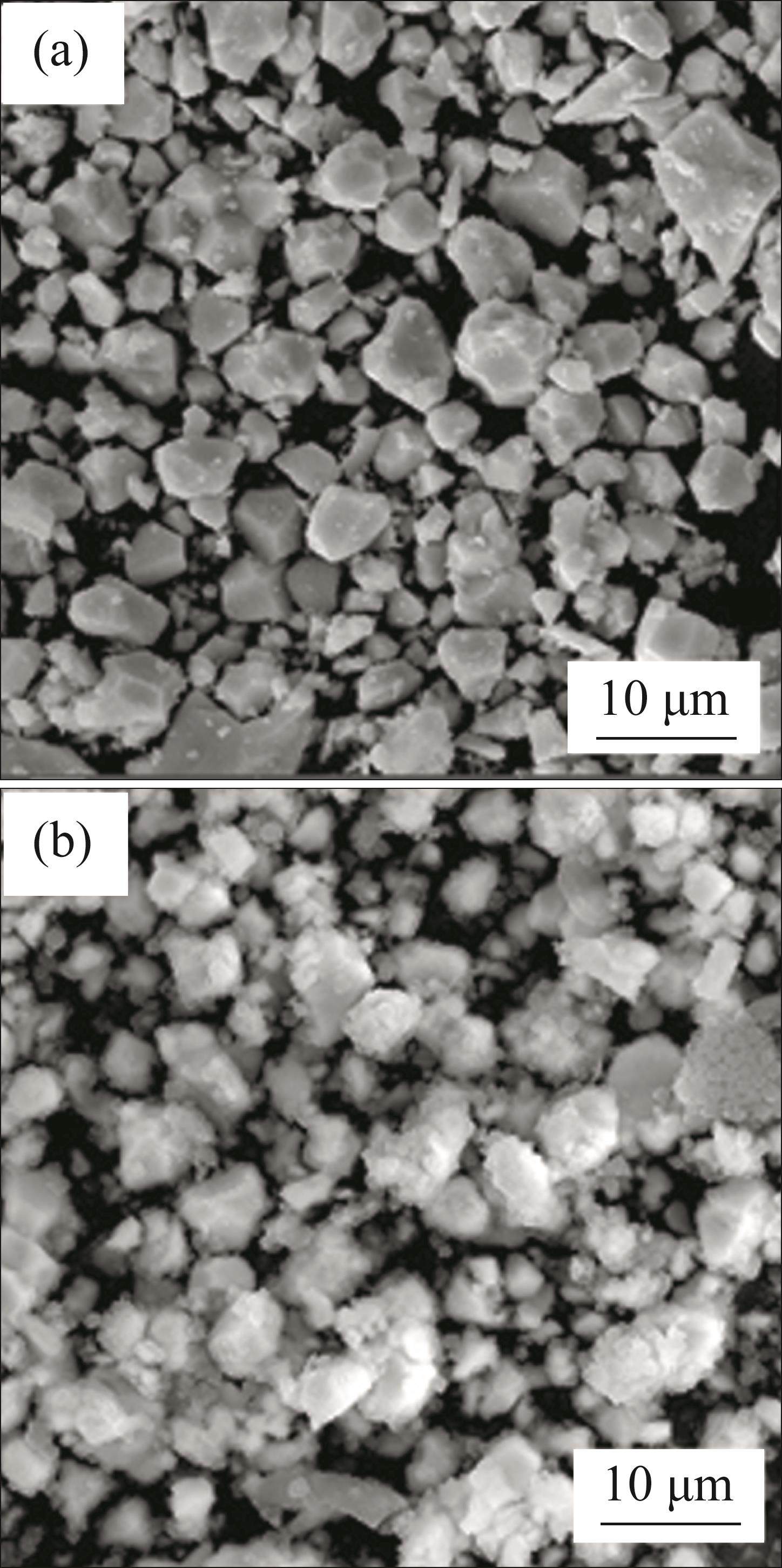
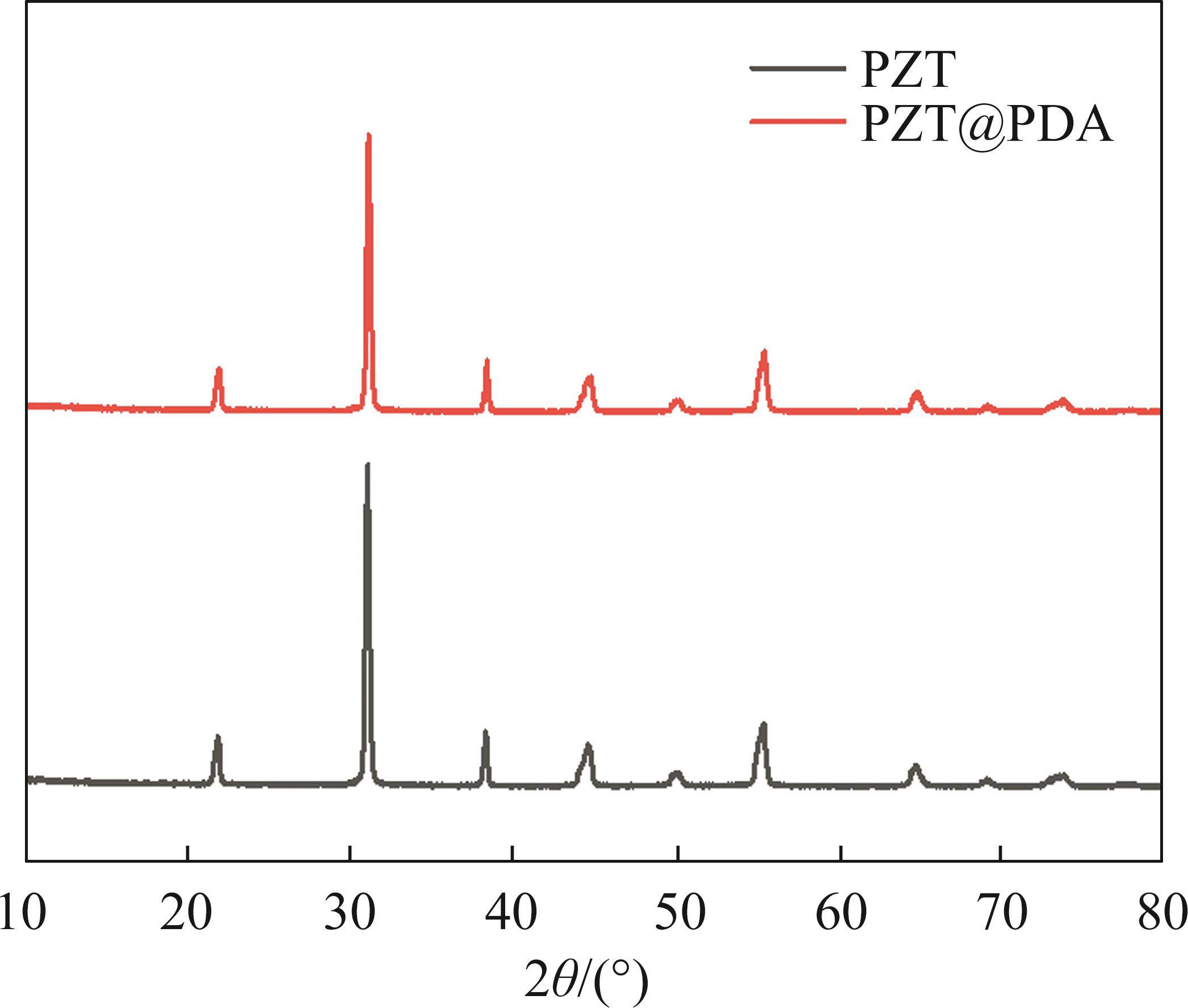
Figure 2 shows the XRD characterization patterns of PZT powders before and after modification, and both of them have diffraction peaks with the same position. It indicates that PDA modification does not affect the crystal structure of powders. The polymeric adsorption of dopamine on the PZT surface is mainly realized by electrostatic interactions. It is a physical adsorption phenomenon that does not affect the crystal structure, but the encapsulated organic shells cause the intensity of the characteristic diffraction peaks to undergo a slight degradation.
In order to investigate the effect of PDA surface coating on the dispersion and compatibility of PZT in PVDF matrix, the surface morphology of the composite film was characterized by SEM in this paper, as shown in Figures 3(a)-(b). It can be seen from the figures that the presence of the PDA shell improves the dispersion of the PZT. Comparing Figures 3(a) and (b), there is a tendency for the size of PZT particles to become smaller after coating PDA, while the distribution is more uniform. However, it is less obvious in the magnified electron microscope images, probably because the PZT has a large size, that does not easily aggregate in PVDF. In addition, the PZT@PDA can be better embedded inside the PVDF matrix. Self-polymerization reaction occurs in dopamine (DA) in neutral or alkaline environment and it adsorbs to the surface of PZT to form PDA, PDA as the cladding shell of PZT can be used as a transition layer to ease the difference between it and PVDF that improves the compatibility of composites [27]. As shown in Figure 3(c), the surface of the prepared PVDF/PZT composite films possessed a porous structure. The reason is that when ink formulated with DMSO is printed, the low temperature of printing platform causes the DMSO solvent to solidify in printed film. When the film is placed in an oven to remove the solvent, the solidified DMSO gradually melts and evaporates due to its low melting point, leaving a large number of holes in PVDF film.

Figure 4 shows the FTIR spectra of PVDF/PZT composite films. After the addition of 1 wt.% unmodified PZT to PVDF, the characteristic absorption peaks of the α phase appeared at 614, 763 and 975 cm-1. It indicates that the unmodified PZT inhibited the formation of polar phase and made it more inclined to form stable α phase. After the modification of PZT with PDA surface coating, the intensity of the characteristic absorption peaks of the α phase appeared to be attenuated compared with that before the modification. The reason for this is that the presence of the PDA shell improves the dispersion of PZT in PVDF, and the dispersed PZT is able to induce nucleation of the polar phase. As the content of PZT@PDA increased from 1 wt.% to 5 wt.%, the intensity of the characteristic absorption peaks of α phase gradually weakened, whereas the intensity of the characteristic absorption peaks of the β phase at 1274 cm-1 gradually increased.
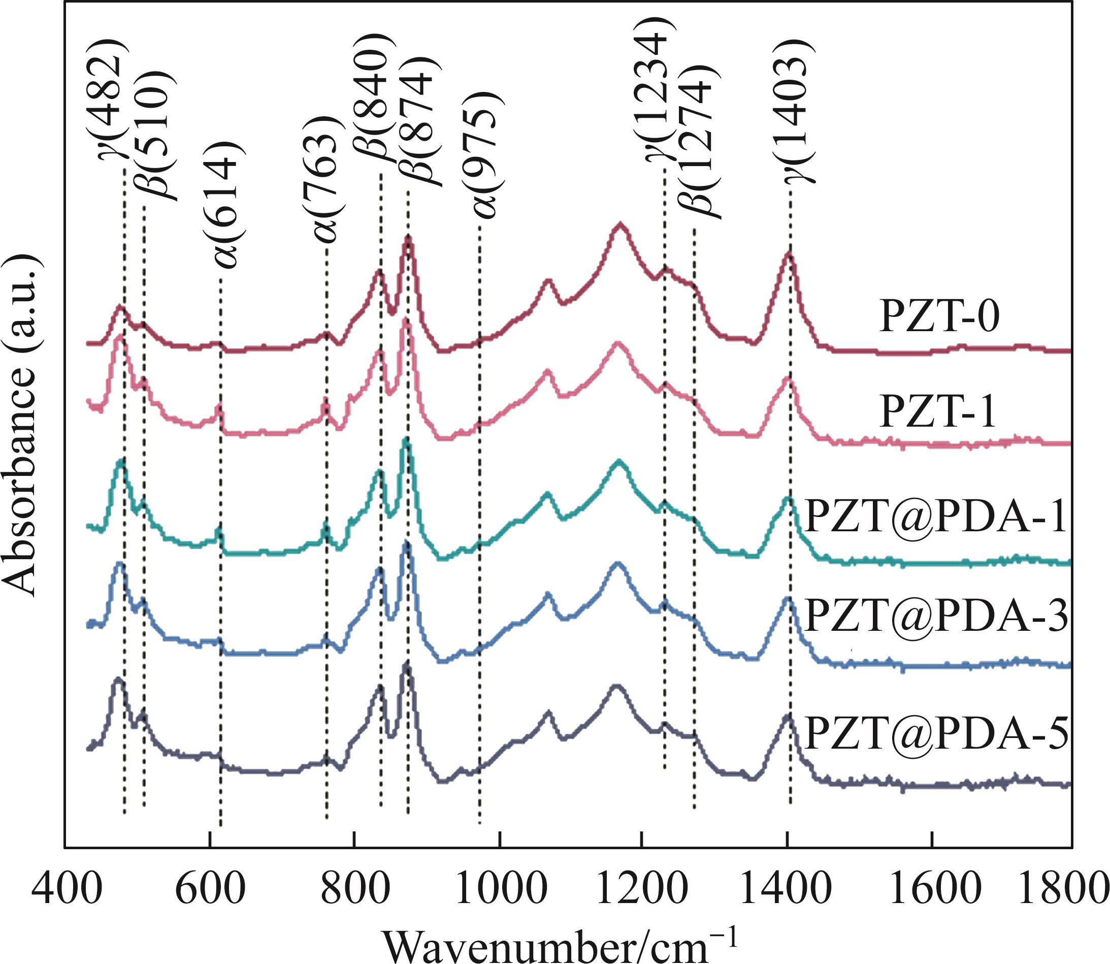
Using the FTIR spectral results, the relative content of polar crystalline phases in PVDF can be quantitatively calculated according to the Beer-Lambert law [28] as follows:

where 


Since the broad peak appearing at 830- 840 cm-1 is usually the sum of the characteristic absorption peak of the γ phase at 833 cm-1 and the characteristic absorption peak of the β phase at 840 cm-1, in order to obtain the relative content of the β-crystalline phase, Eq. (2) was used for the calculation, the equation is as follows:

where 


The calculated results are shown in Table 2. The F(β) of the PVDF film with 5 wt.% PZT@PDA is 40.83%, while the F(β) of the PVDF film with 1 wt.% PZT@PDA is only 34.62%. Compared with unmodified PZT, PZT@PDA is more favorable to promote the transition from α phase to β phase.
| Sample | F(α)/% | F(β)/% | F(γ)/% |
|---|---|---|---|
| PZT-0 | 25.77 | 39.02 | 35.2 |
| PZT-1 | 35.54 | 34.62 | 29.84 |
| PZT@PDA-1 | 33.17 | 36.10 | 30.73 |
| PZT@PDA-3 | 25.66 | 40.12 | 34.22 |
| PZT@PDA-5 | 24.75 | 40.83 | 34.42 |
Figure 5 shows the DSC curves of PVDF/PZT based films. Tm values of all the films show a decrease after the addition of PZT. It is because the presence of PZT hinders the growth of nuclei and imperfect crystallization results in a lower melting point.
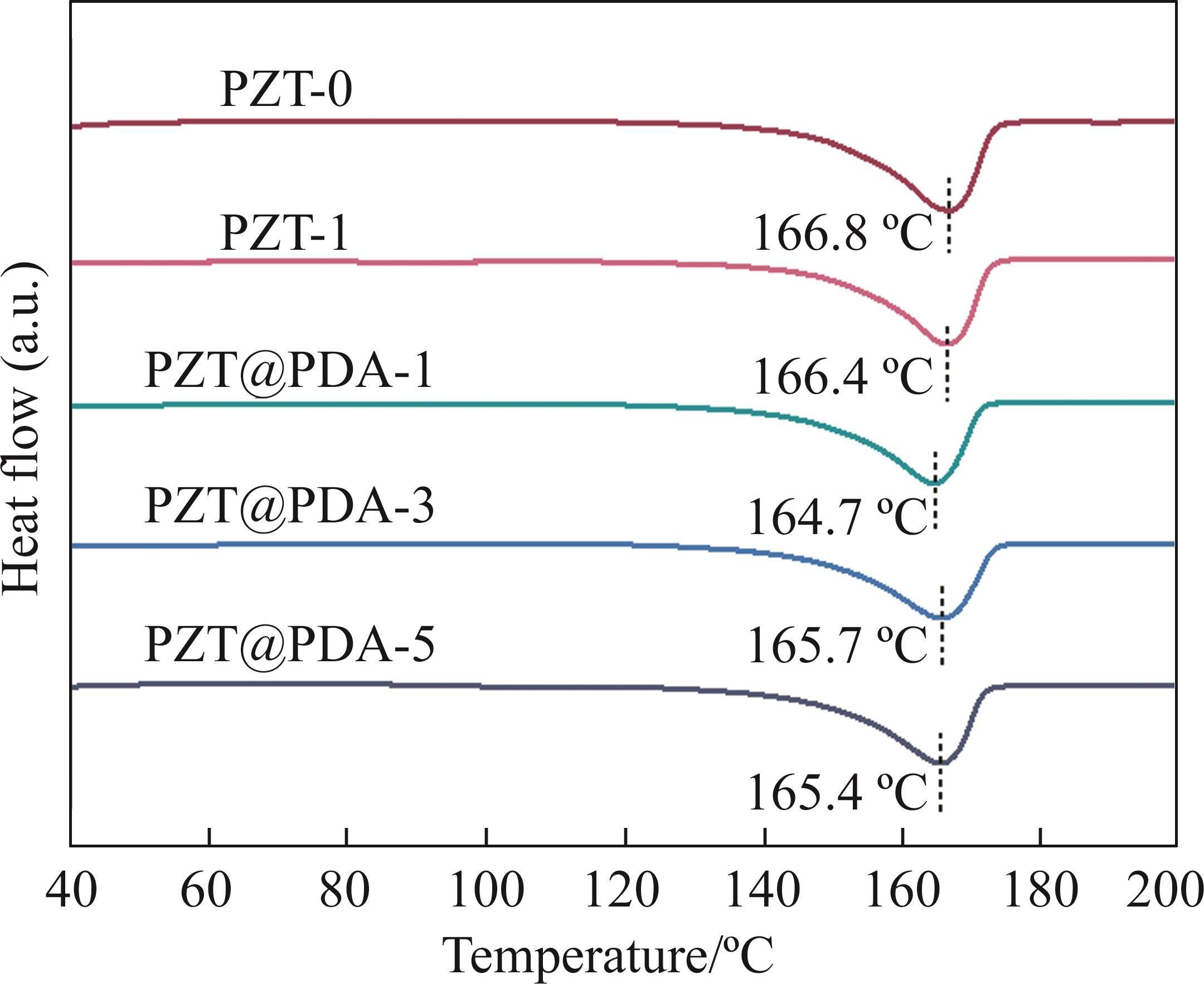
Based on the enthalpy values of the samples obtained from the tests, the crystallinity of the PVDF/PZT-based composite films can be calculated by Eq. (3) as follows:

where

Combined with the previously obtained F(β), the β phase content can be obtained, and the calculated results are shown in Table 3. Since the addition of fillers has a dual effect on PVDF crystallization, fillers can acting as nucleating agents to increase the probability of PVDF crystallization, but fillers can become heterogeneous particles to interfere with the crystallization process. From the calculation results of crystallinity, it can be seen that the crystallinity of the composite films does not change much after the addition of PZT, indicating that the two roles are in a relatively balanced state. The PVDF with 5 wt.% modified PZT has the highest β phase content (28.09%), owing to the fact that the PDA modification resulted in more polar hydroxyl functional groups on the surface of the PZT, and the hydroxyl groups induced the generation of polar phases by creating strong O—H…F—C hydrogen bonding interactions between the hydroxyl groups and the PVDF molecular chains [32]. Meanwhile, the PDA shell hinders the agglomeration of PZT and improves the compatibility between PZT and the matrix. The dispersed PZT can acting as nucleating agents, increasing the probability of crystallization and promoting the generation of polar phases.
| Sample | F(β)/% | Xc/% | Xc(β)/% |
|---|---|---|---|
| PZT-0 | 39.02 | 67.61 | 26.38 |
| PZT-1 | 34.62 | 66.55 | 23.04 |
| PZT@PDA-1 | 36.1 | 67.56 | 24.39 |
| PZT@PDA-3 | 40.12 | 66.37 | 26.63 |
| PZT@PDA-5 | 40.83 | 68.80 | 28.09 |
3.2 Electrical properties
Figure 6 shows the results of the dielectric properties characterization of PVDF/PZT composite films with different fillers. In the frequency range of 1 kHz-1 MHz, the dielectric constant of the film decreases with frequency and the dielectric loss increases with frequency, this is associated with the dielectric relaxation phenomenon occurring in the dipole in the PVDF matrix. It is noteworthy that the dielectric constant of PVDF film with PZT@PDA decreased more drastically in the high frequency band, probably due to the adhesive properties of PDA [33]. When the frequency increases, PDA exerts an inhibitory effect on the dipole steering, making it even more incapable of keeping up with the change in the external electric field and exacerbating the dielectric relaxation phenomenon.
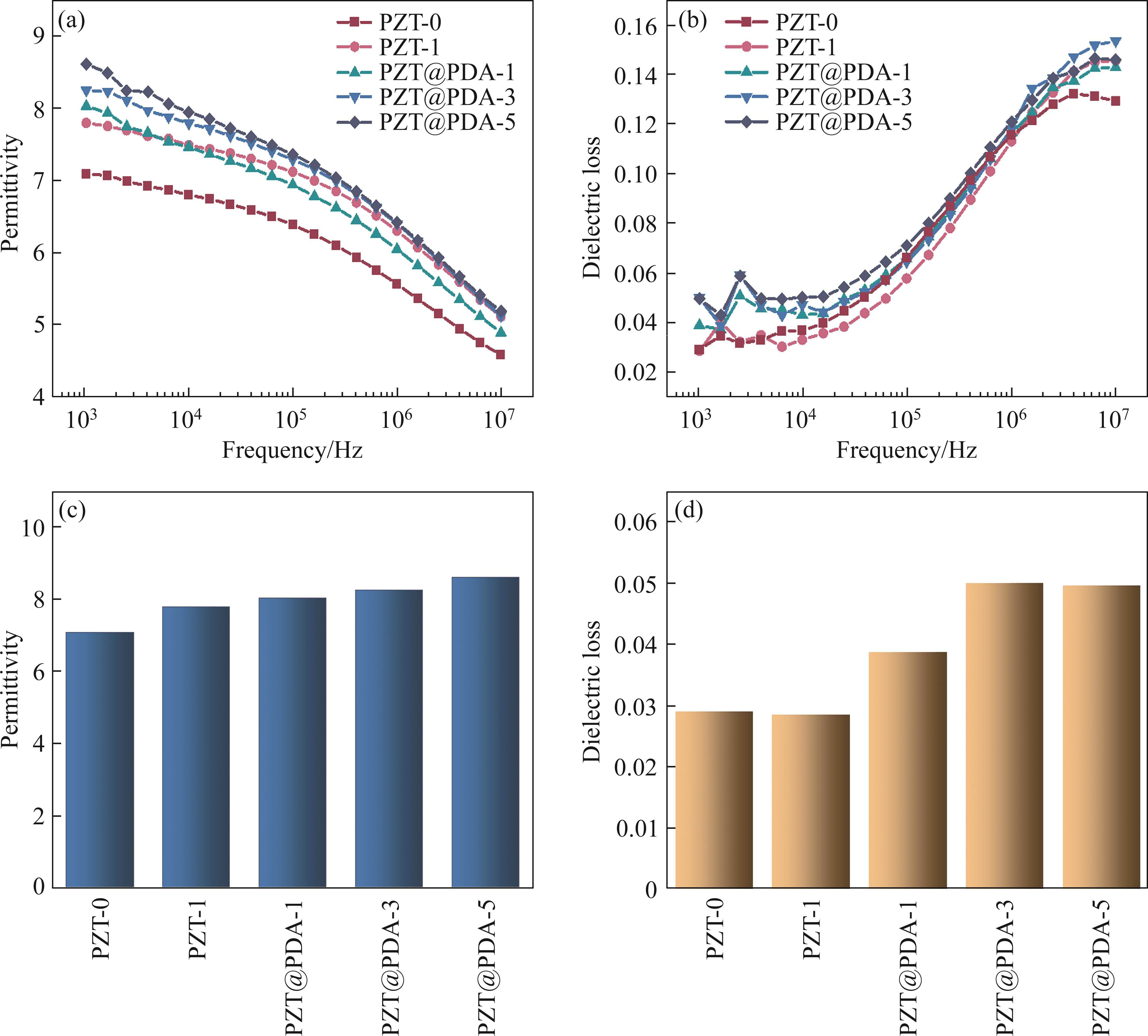
At a frequency of 1 kHz, the value of dielectric constant of the composite film with 1 wt.% PZT is higher than that of the pure PVDF film. Due to the formation of a large number of interfaces between ceramic particles and polymer matrix inside the composite material, electrons and ions can easily gather at these interfaces, forming interfacial polarization phenomenon, and improving the dielectric constant. After the addition of PZT@PDA, PZT/PDA and PDA/PVDF dual interfaces exist in the PVDF matrix at the same time, and the increase in the interfacial specific surface area improves the interfacial polarization phenomenon. While increasing the addition amount of PZT@PDA can also increase the place of occurrence of interfacial polarization and achieve the effect of enhanced interfacial polarization. In addition, the polar phase induced by PZT@PDA contributes a significant amount of dipole polarization. Therefore, PVDF composite film with 5 wt.% PZT@PDA has the highest dielectric constant (8.61).
Figure 7 shows the hysteresis loop of the PVDF/PZT composite films at 200 MV/m electric field strength, as well as the variation of its maximum polarization value, remaining polarization value and coercive field with the electric field. It can be observed that the polarization intensity of the PVDF/PZT composite films change nonlinearly with the electric field intensity, indicating that it has ferroelectricity, and ferroelectric materials belong to a subclass of piezoelectric materials, this also confirms that the PVDF/PZT composite film has piezoelectricity.
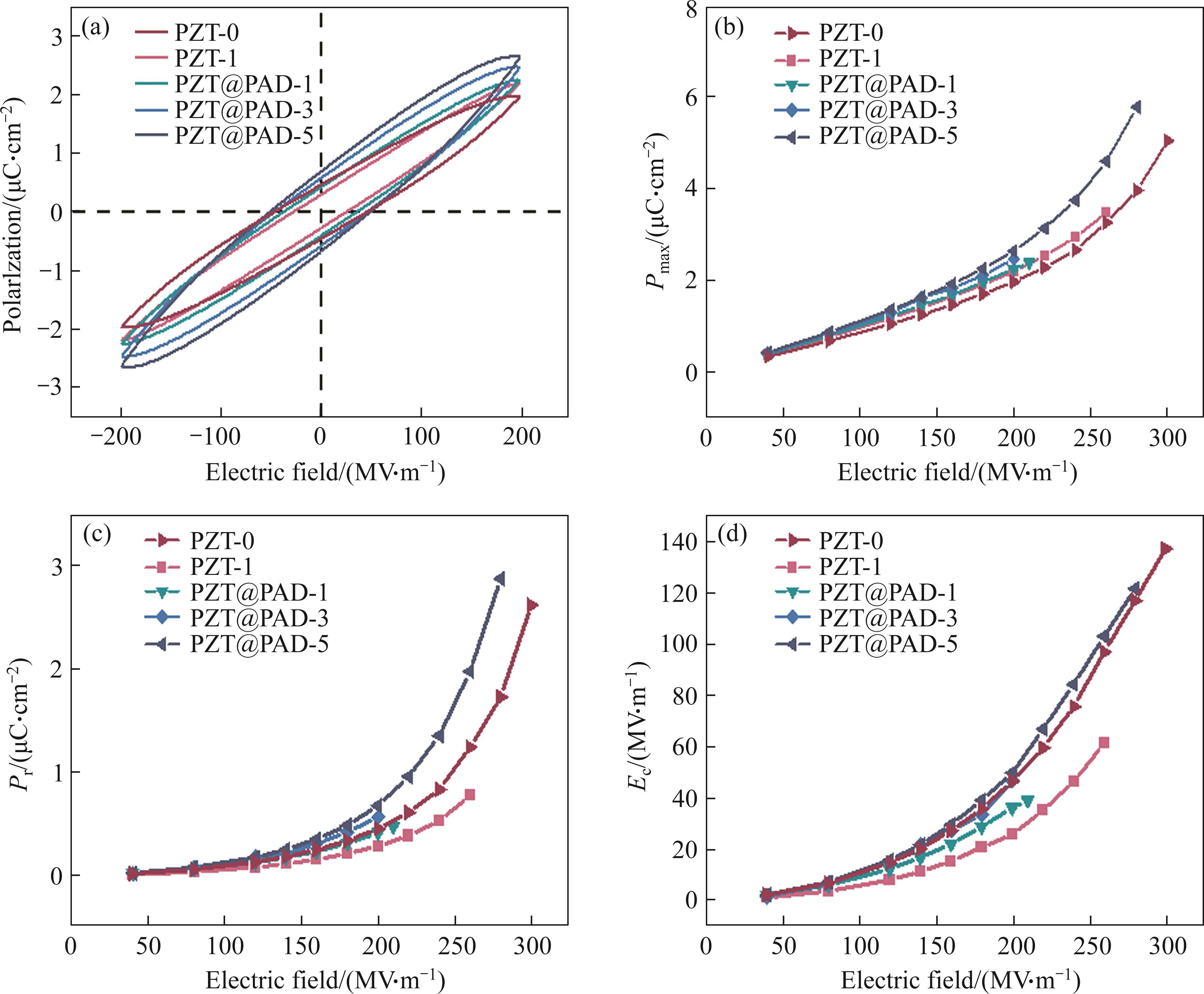
When the electric field strength value is zero, the piezoelectric material still has a certain polarization strength. The magnitude of the residual polarization value (Pr) characterizes the strength of the piezoelectricity possessed by the PVDF/PZT piezoelectric material. The residual polarization value of PVDF composite film with 1 wt.% PZT is rather reduced compared to pure PVDF, the reason is that the added PZT hinders the rotation of the PVDF molecular chain in the matrix, resulting in a reduction of polar phase content. The residual polarization value of the composite piezoelectric film is improved after PDA-coating modification of PVDF. This is mainly beneficial to the fact that the surface coating provides more polar groups on the surface of PZT particles, and the generated hydrogen bonding between polar groups and —CF2— groups induces the generation of more polar phases. The Pr values of the composite films with 1 wt.%, 3 wt.% and 5 wt.% additions are 0.4168, 0.5698 and 0.6803 μC/cm2, respectively. With the increase of PZT@PDA, the films possessed higher ferroelectricity. The increase in ferroelectricity is due to the good dispersion and compatibility of the large number of PZT@PDA in the matrix, and provides more nucleation sites. The increase in the β phase content and the ferroelectric properties possessed by PZT itself results in optimal ferroelectric properties for the 5 wt.% PZT@PDA composite film.
4 Conclusions
In this paper, PVDF films containing PZT were prepared by direct ink writing, and the effect of PZT content on the crystallization behavior and electrical properties of the composite films was investigated. The specific conclusions are as follows:
1) Modification of PZT powders with PDA surface coating can improve the agglomeration of fillers between the matrix, and a large number of polar groups generated by the surface coating interact the —CF2— groups in PVDF, inducing the generation of polar β phase due to hydrogen bonding formed in the interaction. The composite film with 5 wt.% PZT@PDA has the highest β phase content (28.09%).
2) PZT filler has a dual effect on the crystallization behavior of PVDF, well-dispersed filler plays a role of nucleating agent to promote the generation of polar phases in PVDF/PZT composite film, and agglomerated filler also acts as an impurity hindering the growth of nuclei to reduce crystallinity.
3) PZT filler participates in the construction of multiple interfaces, and provides more sites for the occurrence of interfacial polarization and thus improving the electrical properties of films, which is beneficial to the improvement of the dielectric and ferroelectric properties of the films. The PVDF composite film with 5 wt.% PZT@PDA possesses the highest dielectric constant (8.61) and residual polarization value (0.6803 μC/cm2).
PVDF - TrFE/SiO2 composite film bulk acoustic resonator for frequency-modulated sensor application
[C]//A renewable low-frequency acoustic energy harvesting noise barrier for high-speed railways using a Helmholtz resonator and a PVDF film
[J]. Applied Energy, 2018, 230: 52-61. DOI: 10.1016/j.apenergy.2018.08.080.Flexible piezotronic strain sensor
[J]. Nano Letters, 2008, 8(9): 3035-3040. DOI: 10.1021/nl802367t.Fully-printed piezoelectric devices for flexible electronics applications
[J]. Advanced Materials Technologies, 2021, 6(3): 2001020. DOI: 10.1002/admt.202001020.A flexible piezoelectric pressure sensor based on PVDF nanocomposite fibers doped with PZT particles for energy harvesting applications
[J]. Ceramics International, 2020, 46(12): 19669-19681. DOI: 10.1016/j.ceramint.2020.03.210.Self-poled hBN-PVDF nanofiber mat-based low-cost, ultrahigh-performance piezoelectric nanogenerator for biomechanical energy harvesting
[J]. ACS Applied Electronic Materials, 2020, 2(7): 1970-1980. DOI: 10.1021/acsaelm.0c00272.Acoustic energy harvesting and sensing via electrospun PVDF nanofiber membrane
[J]. Sensors, 2020, 20(11): 3111. DOI: 10.3390/s20113111.Piezoelectric nanotransducers
[J]. Nano Energy, 2019, 59: 730-744. DOI: 10.1016/j.nanoen.2019. 03.027.A flexible piezoelectric nanogenerator using conducting polymer and silver nanowire hybrid electrodes for its application in real-time muscular monitoring system
[J]. Sensors and Actuators A: Physical, 2019, 299: 111575. DOI: 10.1016/j.sna.2019. 111575.Piezoelectric properties and ferroelectric hysteresis effects in uniaxially stretched nylon-11 films
[J]. Journal of Applied Physics, 1984, 56(9): 2419-2425. DOI: 10.1063/1.334294.Synthesis of biodegradable and electroactive multiblock polylactide and aniline pentamer copolymer for tissue engineering applications
[J]. Biomacromolecules, 2008, 9(3): 850-858. DOI: 10.1021/bm7011828.Enhanced peripheral nerve regeneration through a poled bioresorbable poly(lactic-co-glycolic acid) guidance channel
[J]. Journal of Neural Engineering, 2004, 1(2): 91-98. DOI: 10.1088/1741-2560/1/2/004.The piezoelectricity of poly (vinylidene fluoride)
[J]. Japanese Journal of Applied Physics, 1969, 8(7): 975. DOI: 10.1143/jjap.8.975.Composites, fabrication and application of polyvinylidene fluoride for flexible electromechanical devices: A review
[J]. Micromachines, 2020, 11(12): 1076. DOI: 10.3390/mi1112 1076.Wireless piezoelectric devices based on electrospun PVDF/BaTiO3 NW nanocomposite fibers for human motion monitoring
[J]. Nanoscale, 2018, 10(37): 17751-17760. DOI: 10.1039/c8nr05292a.Characterization of PZT/PVDF composite film as functional material
[J]. IEEE Sensors Journal, 2018, 18(12): 5067-5072. DOI: 10.1109/JSEN.2018.2830115.Structural energetic properties of Al/PVDF composite materials prepared using fused filament fabrication
[J]. Propellants, Explosives, Pyrotechnics, 2021, 46(4): 670-678. DOI: 10. 1002/prep.202000183.Enhanced β-phase in direct ink writing PVDF thin films by intercalation of graphene
[J]. Journal of Inorganic and Organometallic Polymers and Materials, 2020, 30(5): 1497-1502. DOI: 10.1007/s10904-019-01310-0.Characterization of piezoelectric properties of Ag-NPs doped PVDF nanocomposite fibres membrane prepared by near field electrospinning
[J]. Combinatorial Chemistry & High Throughput Screening, 2022, 25(4): 720-729. DOI: 10.2174/1386207324666210302100728.Multifunctional sensing using 3D printed CNTs/BaTiO3/PVDF nanocomposites
[J]. Journal of Composite Materials, 2019, 53(10): 1319-1328. DOI: 10.1177/0021998318800796.Enhanced dielectric properties of three phase dielectric MWCNTs/BaTiO3/PVDF nanocomposites for energy storage using fused deposition modeling 3D printing
[J]. Ceramics International, 2018, 44(8): 9037-9044. DOI: 10.1016/j.ceramint.2018.02.107.Mortise-tenon joint structured hydrophobic surface-functionalized Barium titanate/polyvinylidene fluoride nanocomposites for printed self-powered wearable sensors
[J]. Nanoscale, 2021, 13(4): 2542-2555. DOI: 10.1039/d0nr07525f.Polyvinylidene fluoride energy harvester with boosting piezoelectric performance through 3D printed biomimetic bone structures
[J]. ACS Sustainable Chemistry & Engineering, 2021, 9(22): 7561-7568. DOI: 10.1021/acssuschemeng.1c01305.Combining solid-state shear milling and FFF 3D-printing strategy to fabricate high-performance biomimetic wearable fish-scale PVDF-based piezoelectric energy harvesters
[J]. ACS Applied Materials & Interfaces, 2022, 14(13): 15346-15359. DOI: 10.1021/acsami.2c02491.3D printing of polyvinylidene fluoride/photopolymer resin blends for piezoelectric pressure sensing application using the stereolithography technique
[J]. MRS Communications, 2019, 9(3): 1115-1123. DOI: 10.1557/mrc.2019.109.Electrical properties of PVDF films fabricated by direct ink writing
[J]. Journal of Central South University, 2023, 30(5): 1477-1489. DOI: 10.1007/s11771-023-5340-6.Effect of crystallization temperature on the crystalline phase content and morphology of poly(vinylidene fluoride)
[J]. Journal of Polymer Science Part B: Polymer Physics, 1994, 32(5): 859-870. DOI: 10. 1002/polb.1994.090320509.Investigation on the effect of γ-irradiation on the dielectric and piezoelectric properties of stretchable PVDF/Fe-ZnO nanocomposites for self-powering devices
[J]. Soft Matter, 2018, 14(43): 8803-8813. DOI: 10.1039/c8sm01655k.Determination of the crystalline phases of poly(vinylidene fluoride) under different preparation conditions using differential scanning calorimetry and infrared spectroscopy
[J]. Journal of Applied Polymer Science, 2003, 89(4): 1093-1100. DOI: 10.1002/app.12267.Fabrication and characterization of meltblown poly(vinylidene difluoride) membranes
[J]. ACS Applied Polymer Materials, 2020, 2(7): 2849-2857. DOI: 10.1021/acsapm.0c00395.Core-shell structured biopolymer@BaTiO3 nanoparticles for biopolymer nanocomposites with significantly enhanced dielectric properties and energy storage capability
[J]. The Journal of Physical Chemistry C, 2015, 119(49): 27330-27339. DOI: 10.1021/acs.jpcc.5b09619.ZHOU Run-kai, YANG Hong, PENG Chao-qun, WANG Ri-chu, ZHANG Dou, FANG Guang-qiang and WANG Xiao-feng declare that they have no conflict of interest.
ZHOU Run-kai, YANG Hong, PENG Chao-qun, WANG Ri-chu, ZHANG Dou, FANG Guang-qiang, WANG Xiao-feng. Electrical properties of PVDF/PZT composite films prepared by direct ink writing [J]. Journal of Central South University, 2025, 32(1): 71-81. DOI: https://doi.org/10.1007/s11771-025-5854-1.
周润恺,杨红,彭超群等.直写成型制备 PVDF/PZT 复合薄膜的电学性能[J].中南大学学报(英文版),2025,32(1):71-81.

