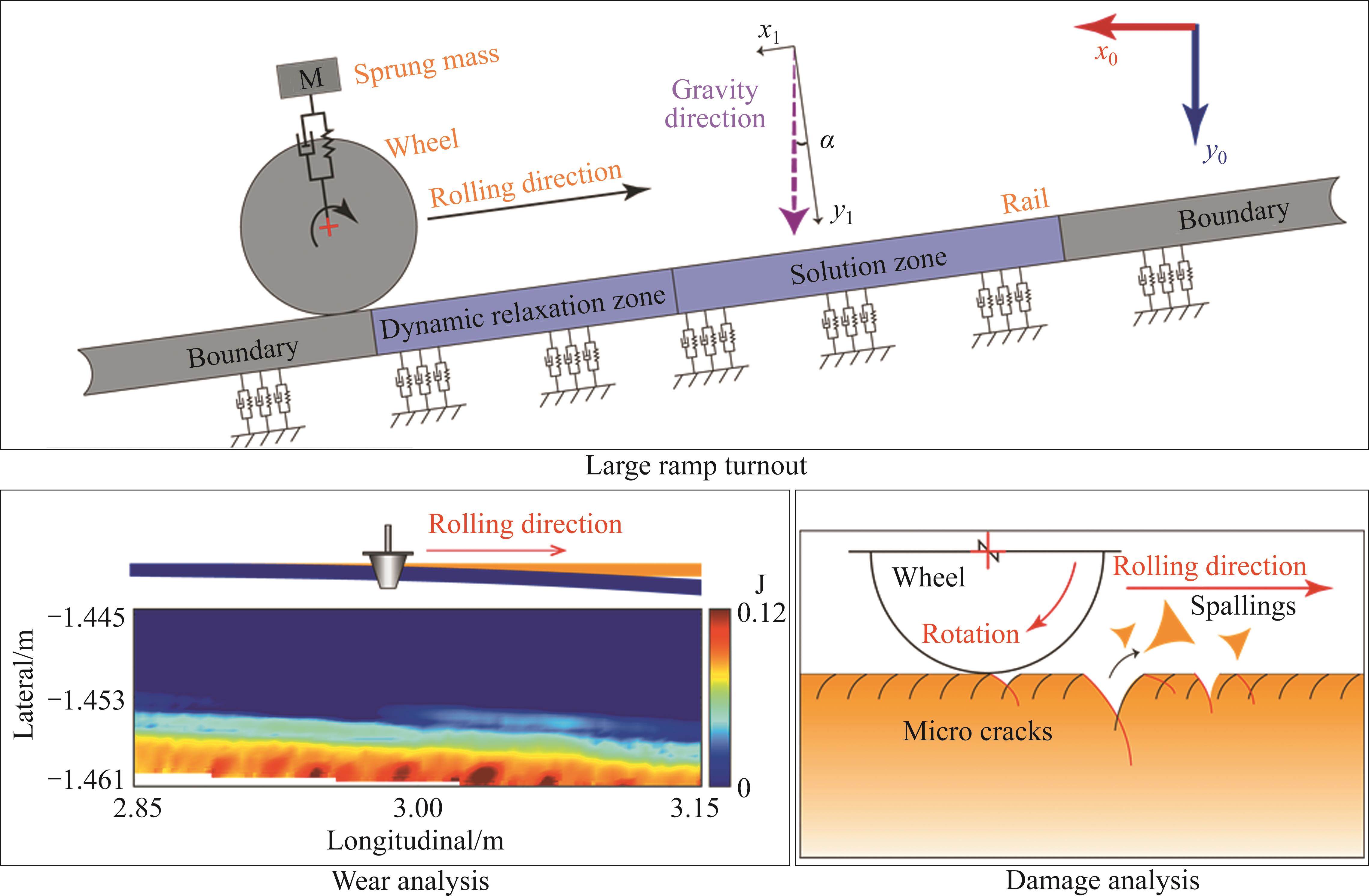
1 Introduction
A railway turnout comprises switches, frogs, and connecting components, with switches playing a pivotal role in guiding train wheels from the stock rail to the switch rail to facilitate track changes. However, owing to their distinctive structural attributes and the presence of weak constraints on the switch rail, the dynamics of wheel-rail contact within the switch area exhibits heightened complexity compared to standard rail segments. This complexity is further exacerbated during the wheel-rail contact transition and switch rail vibrations, intensifying dynamic interactions between the wheel and rail. Consequently, this phenomenon may significantly contribute to the occurrence of oblique cracks and uneven wear on the switch rail, with direct implications for the operational lifespan of switches and, more critically, for traffic safety, potentially resulting in severe incidents such as train derailments.
To comprehensively assess the mechanical characteristics and damage behavior of turnout switch rails, researchers have conducted extensive investigations [1]. LU et al [2] employed a combination of finite element analysis and multi-body dynamics methods to explore the various types of damage occurring within the switch area. Their findings revealed that a complex interplay of wear, fatigue, and impact contributes to damage in both the switch rails and stock rails. Mitigation strategies were proposed, including reductions in operational speed. XU et al [3] investigated the impact of switch stiffness differentials on wheel-rail dynamic responses, demonstrating that non-uniform stiffness within the switch region substantially amplifies wheel-rail dynamic responses compared to standard rail sections. Additionally, GROSSONI et al [4] argued that the dynamic nature of the switch rail, combined with its continuously varying cross-section along the longitudinal axis, compromises its structural integrity. This structural vulnerability, along with discontinuities in rail geometry and variations in the stiffness of the turnout system support, contributes significantly to the elevated failure rate of switches and associated maintenance costs. SKRYPNYK et al [5] studied the cross-section profile evolution of switch rails under extended service conditions through field tests and numerical simulations, revealing that elevated contact pressure and traction forces from wheel-rail interactions result in rail wear and cumulative plastic deformation, potentially leading to train derailments in cases of pronounced wear. This phenomenon was also observed by LAI et al [6, 7], who linked occurrences of wheel climbing leading to derailments to dynamic changes in the switch rail's longitudinal cross-section and reduced contact angles. MA et al [8] explored the suitability of four non-Hertzian contact methods for calculating turnout damage, concluding that Sichani’s method is more effective at modeling turnout wear and surface rolling contact fatigue. They also noted that turnout rail damage typically occurs under plastic conditions. These studies collectively highlight the unique challenges faced by turnout switches, driven by their pivotal role in guiding wheel movement across tracks. These challenges encompass pronounced wheel-load transitions, wheel-rail impacts, weakly constrained boundary conditions, and compromised cross-sectional integrity of switch rails. Consequently, the issue of switch rail damage assumes considerable significance, with maintenance costs associated with turnout damage accounting for approximately 50% of total maintenance expenditure [9].
Furthermore, as the railway transportation industry continues to advance, there is an inevitable need to lay railway tracks in areas with steep ramps, some of which can reach inclines as high as 44.5‰ in specific sections [10]. ZHAO et al [11] observed that the placement of tracks on substantial ramps significantly influences train braking, starting, and longitudinal impact, while ZHAI et al [12] noted that these ramps intensify wheel-rail forces and vibration acceleration responses. Additionally, WANG et al [13] reported that laying tracks on such ramps leads to a decrease in the wheel-rail adhesion coefficient, suggesting that under these conditions, the wheel-rail contact is more prone to reaching the slip saturation state. This phenomenon aligns with the findings of SONG et al [10], who concluded that the interplay of traction and braking forces on the wheels can induce slip force saturation during uphill and downhill movements, potentially resulting in rail corrugation. MEI et al [14] similarly proposed, in their study, that wheel slippage on the track may be the primary driver of corrugation and introduced a corresponding method for the rapid prediction of such deformities. Consequently, the presence of significant ramps not only affects vehicle performance but also exerts a substantial impact on rail damage, often exacerbating its development. Hence, there exists an urgent need to scrutinize the transient rolling contact behavior and the damage characteristics sustained by wheels and rails in the switch region of high-speed turnouts on large ramps. Such insights are pivotal for guiding the optimal design and maintenance practices for turnouts situated on large ramps.
In this paper, Chapter 2 introduces the establishment of a transient rolling contact finite element model for the wheel-rail system within the switch area under large ramp conditions. In Chapter 3, an analysis of the wheel-rail dynamic response and contact states during high-speed wheel passage through the switch is presented. Chapter 4 delves into a discussion on the wear and damage characteristics of the turnout’s switch rails in the context of large ramps. Finally, Chapter 5 provides concluding insights. The findings from this research can serve as valuable guidance for the maintenance and optimization of high-speed switches situated on substantial ramps.
2 Modelling and validation
2.1 Model description
Figure 1 illustrates a transient rolling contact finite element model representing the wheel-rail interaction within the switch zone. This model was developed using ANSYS/LS-DYNA and comprises half of a wheelset and a single rail side. The car body and bogie are connected to the wheel via a sprung mass through primary suspension. The representation of rubber pads, ties, and ballast beneath the rails has been simplified as fastener springs [15]. This modeling approach’s robustness and accuracy have been extensively validated in prior publications [16-20]. To balance model size and solution precision, adaptive meshing is employed within the wheel-rail contact zone. The minimum mesh size on the upper surface of the curved stock rail is approximately 1 mm. Due to the continuous variation of the switch rail along its longitudinal section, the mesh size within the wheel-rail contact region on the switch rail’s upper surface ranges from 1 mm to 2.7 mm, maintaining a continuous and uniform mesh. The mesh size applied to the wheel treads is approximately 1 mm. The entire model incorporates precise wheel and rail geometries, utilizing LMA treads for the wheels and the commonly used No. 18 high-speed turnout profile for the rails, consistent with China’s high-speed railways. The model’s track length spans 14 m, covering the complete wheel load transition area.
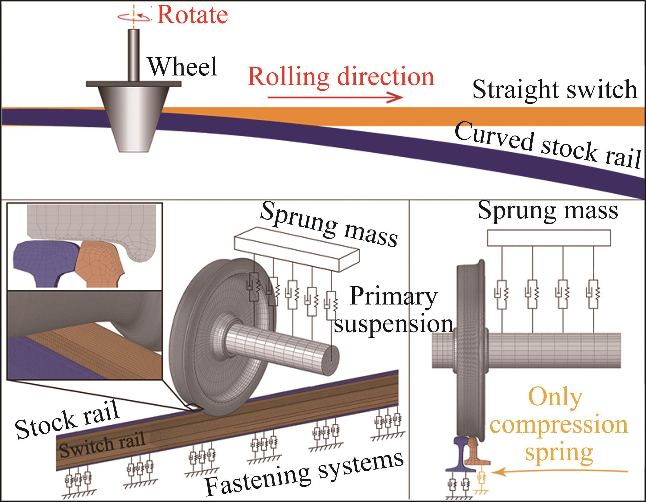
Given its conditional stability, this method requires a very small integration time step [21]. The mechanical characteristics of the wheel-rail contact are resolved using a penalty function face contact algorithm, with longitudinal mechanical behavior between the wheels and rails characterized by Coulomb’s friction law, employing a friction coefficient of 0.3 [22]. The wheels operate at a speed of 250 km/h, and additional model parameters can be found in Table 1.
| Parameter | Value |
|---|---|
| Elastic modulus/GPa | 210 |
| Density/(kg·m-3) | 7850 |
| Poisson ratio | 0.3 |
| Yield strength/MPa | 526 |
| Tangent modulus/GPa | 14.9 |
| Damping constant | 0.0001 |
2.2 Model validation
In the finite element model, we incorporate the component’s gravitational force using gravitational acceleration. Under flat ramp conditions, the gravitational acceleration aligns perpendicular to the longitudinal rail direction, as depicted in Figure 2(a). Here, x0 and y0 denote the global coordinate system, while x1 and y1 represent directions, respectively, parallel and perpendicular to the rail’s longitudinal axis. Both coordinate systems coincide for flat ramps. However, on a large ramp, the entire model effectively rotates by an angle α. While the gravity direction still aligns with the y0 axis of the global coordinate system, it is no longer perpendicular to the rail’s longitudinal direction. Instead, it forms an angle α with the local coordinate system y1. We decompose the gravity acceleration, denoted as G, into x1 and y1 directions, as presented in Eq. (1). Gx1 represents gravitational acceleration parallel to the rail’s longitudinal direction, directly influencing wheel acceleration and deceleration. Gy1 represents gravitational acceleration perpendicular to the rail surface, directly affecting the dynamic load on the rail’s surface.
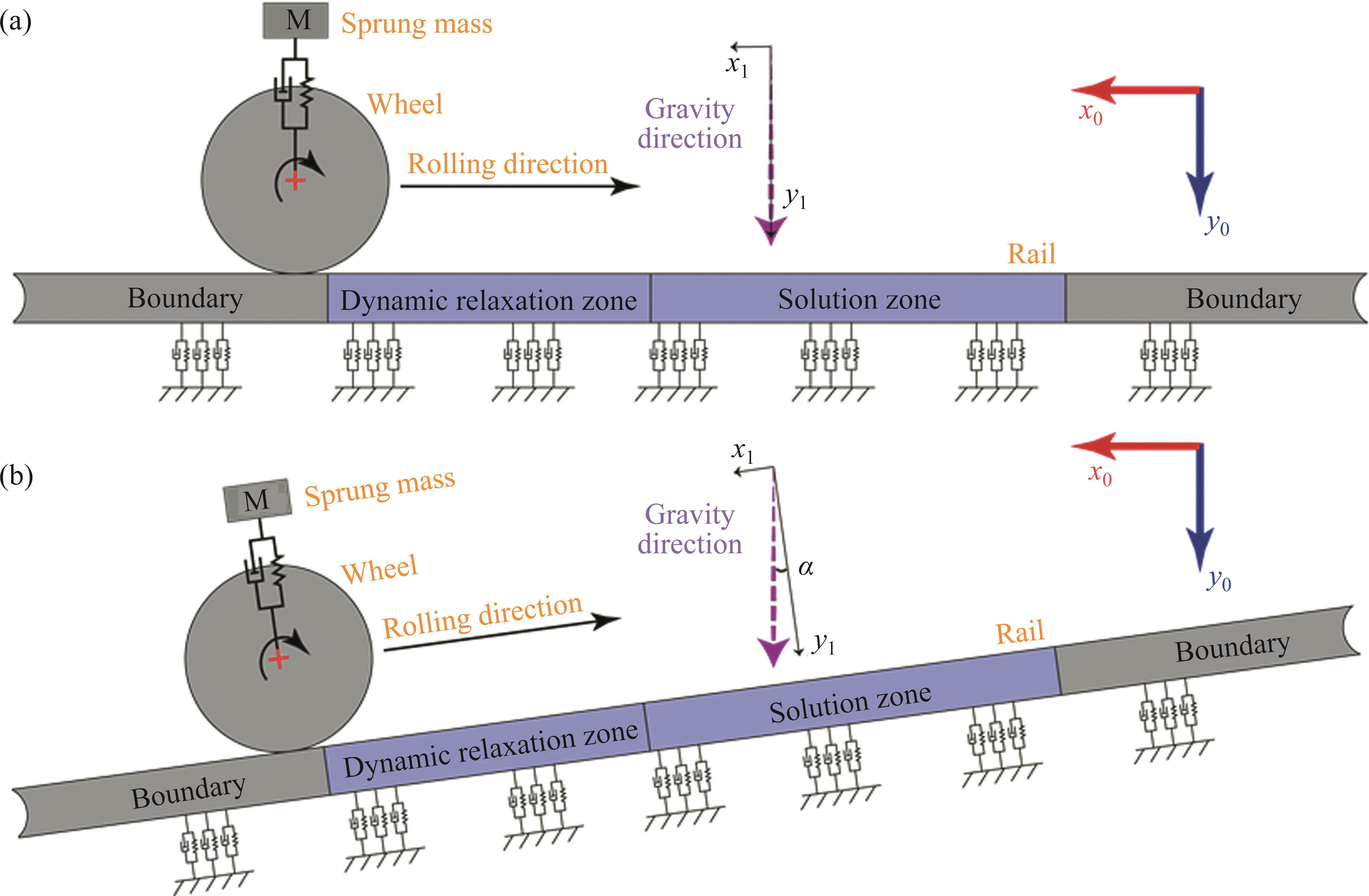
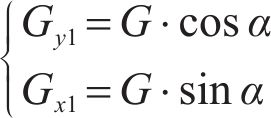
In the formula, G is the gravitational acceleration, and α is the angle of the ramp. This approach involves rotating the model to introduce a gravitational acceleration component along the rail’s longitudinal direction (x1), thereby inducing longitudinal loading of the wheel due to gravity. Another method involves keeping the model stationary while adjusting the gravitational acceleration’s direction by an angle α. This adjustment ensures that the gravitational acceleration components align precisely with those described in Eq. (1), as depicted in Figure 2(b). Importantly, the mechanical models corresponding to Figure 2(b) and Eq. (1) are identical.
In finite element modeling, it is typically more convenient to analyze dynamic responses aligned with the global coordinate system, encompassing parameters such as stress, strain, and deformation. To streamline result analysis, this paper employs Figure 2(b) to compute the dynamic responses of wheel-rail contact under varying ramps. In accordance with the design specifications for high-speed railroads, the gradient of the track cannot exceed 30‰. Therefore, this study incorporates a safety margin of 10‰. The analysis encompasses gradients ranging from 0‰ to 40‰, with increments of 10‰, to thoroughly evaluate the impact of varying ramps on railway operations. The simulations are conducted at a speed of 250 km/h, encompassing a wide spectrum of ramp conditions relevant to railway scenarios. To ensure uniform wheel speed on the track, distinct traction torques are applied for different ramps to counteract the longitudinal gravity component. Specific model parameters are detailed in Table 2.
| Ramp | Longitudinal component of gravity/(m·s-2) | Traction torque/ (N·m) |
|---|---|---|
| 0‰ | 0 | 0 |
| 10‰ | 0.098 | 1941 |
| 20‰ | 0.196 | 3882 |
| 30‰ | 0.294 | 5821 |
| 40‰ | 0.392 | 7759 |
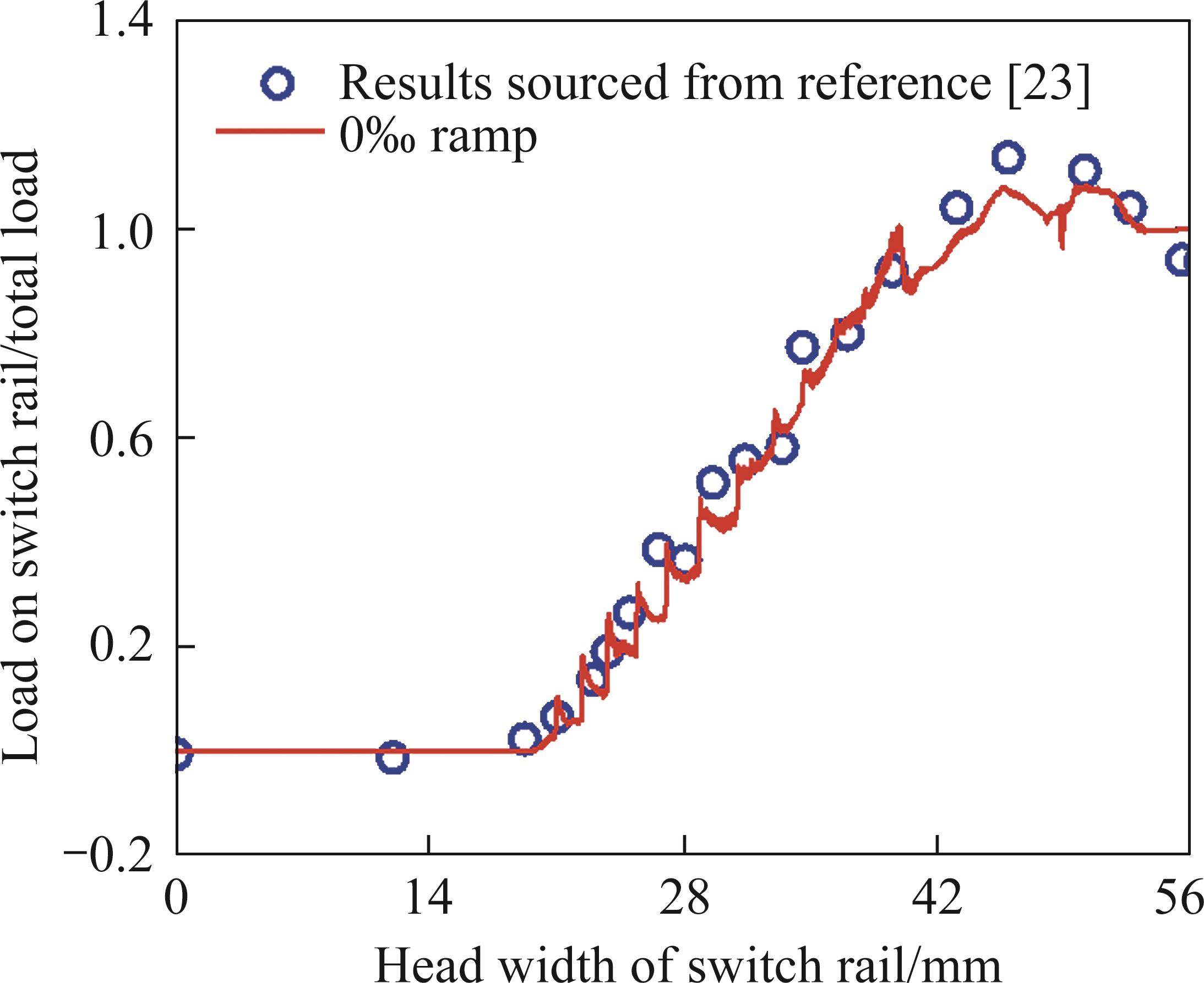
Considering the relative weakness of the switch rail’s cross-section, it is important to assess its ability to support wheel loads, especially in regions with narrow top widths. Consequently, this paper presents line graphs depicting the proportion of vertical force supported by the switch rail under varying top widths. The obtained results, both under flat ramp conditions and in accordance with those from the literature [23], are overlaid within the same coordinate system, as illustrated in Figure 3. Analysis of the figure reveals a high degree of concurrence between the two datasets, with overlapping wheel load transition areas and nearly identical proportions of load borne by the switch rail. This alignment serves as an initial validation of the modeling approach employed in this paper.
3 Results analysis
3.1 Wheel-rail forces
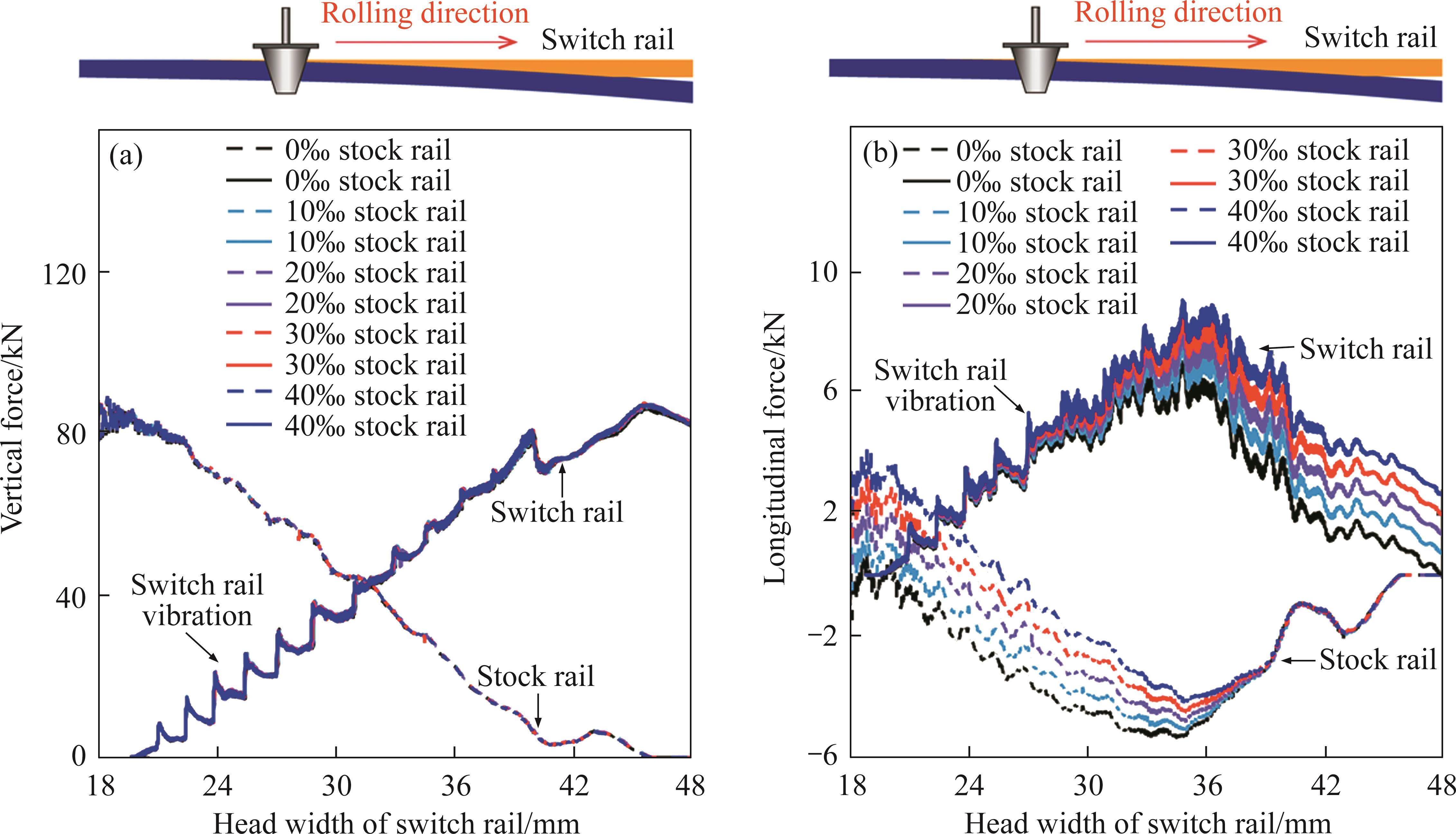
In both scientific and engineering domains, the wheel-rail contact force constitutes a pivotal parameter for investigating wheel-rail interactions. Figure 4(a) presents the vertical wheel-rail contact force at various top widths of the switch rail. The figure reveals that the influence of the ramps on both the wheel load transition area and the vertical force is negligible. Under varying ramp conditions, the switch rail begins to bear the load at a top width of 18-20 mm, with the transition of wheel load completing at a top width of 43-45 mm. The vertical force profiles of the wheel rails exhibit substantial overlap across all ramp scenarios. This phenomenon can be attributed to the fact that even in the case of a steep 40‰ ramp, the difference in the gravitational acceleration component perpendicular to the rail’s surface, compared to that of flat ramp conditions, amounts to a mere 0.00783 m/s² (calculated using Eq. (1)). This disparity is significantly smaller than the standard 9.8 m/s². Therefore, substantial engineering ramps exhibit an ignorable impact on the wheel-rail interaction perpendicular to the rail surface. However, as elucidated in Figure 4(b), the effect of the ramp on the longitudinal wheel-rail interaction is notably pronounced. The figure clearly demonstrates that for the switch rail’s top width below 18 mm or exceeding 45 mm, an increase in ramp gradient corresponds to a proportional rise in the wheel-rail longitudinal force. This longitudinal force magnitude aligns with the longitudinal component of gravity. Additionally, during the process of wheel load transfer, both the longitudinal force and vertical force on the switch rail exhibit uniform fluctuations. This signifies that the wheel load transfer is not linear from the stock rail to the switch rail but involves periodic load fluctuations—characterized by load increases, decreases, increases, and wave-like patterns. This regular fluctuation of wheel-rail forces inevitably subjects the switch rail to cyclic loading. On one hand, this cyclic loading may lead to periodic uneven wear on the rail surface, resulting in switch rail corrugation. On the other hand, it may exacerbate rolling contact fatigue on the rail surface.
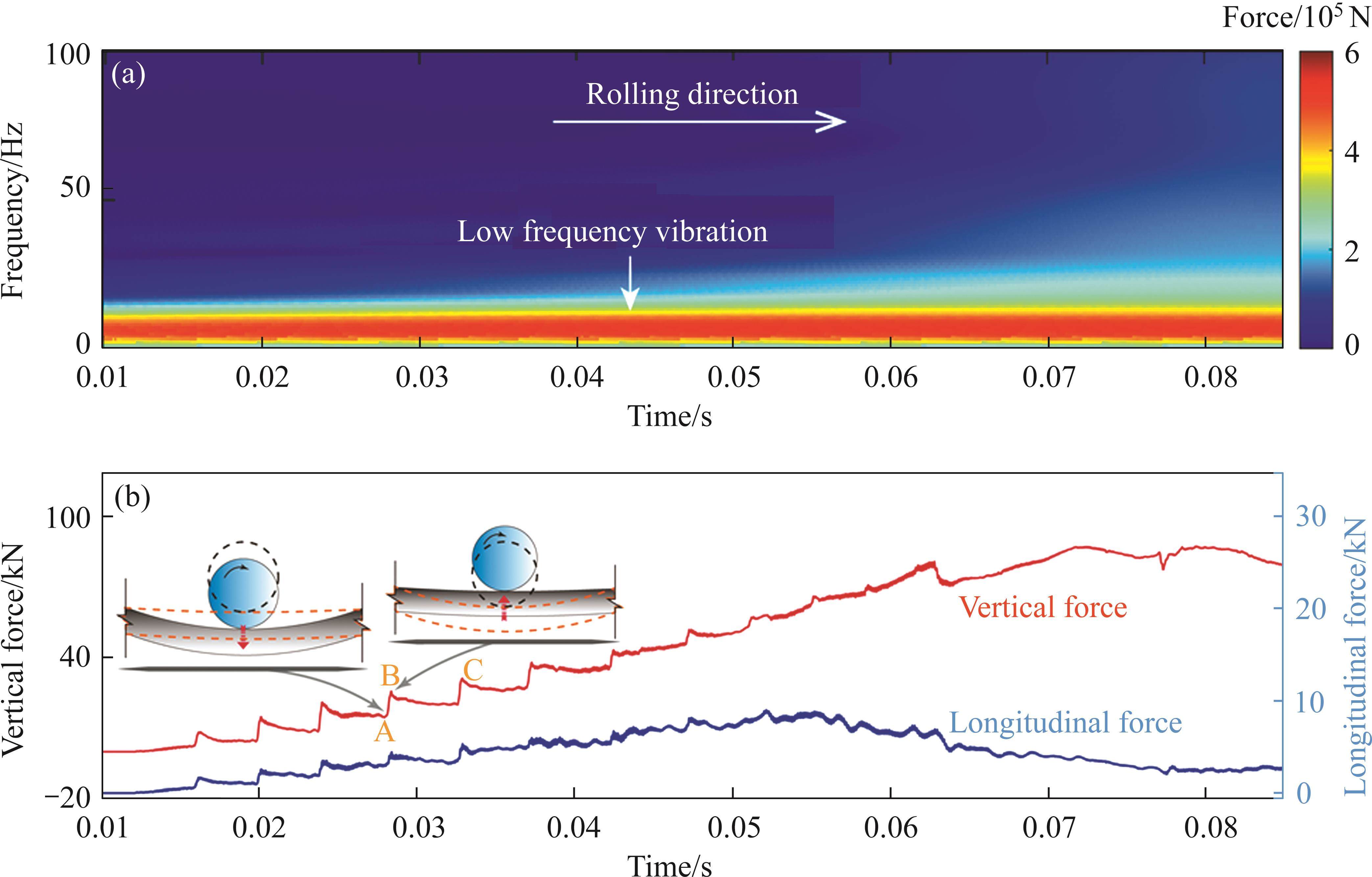
To further investigate the distribution law of the wheel-rail contact force on the switch rail and its associated impact, we present in Figure 5 the wheel-rail contact force and its corresponding time-frequency diagram under a 40‰ ramp condition. Examination of these plots reveals that the vibration patterns of both the vertical and longitudinal forces on the switch rail exhibit remarkable similarity, characterized by low-frequency vibrations of less than 25 Hz. In Figure 5(b), a notable observation is the distance between points B and C, approximately measuring 0.306 m, which closely aligns with the switch rail corrugation wavelength previously documented in the literature [24] as 0.3 m. Consequently, this prompts the suspicion that this low-frequency vibration significantly contributes to the formation of corrugations within the wheel-loaded transition zone of the switch rail. Under the substantial wheel load, the switch rail descends, initiating elastic deformation within the rubber pad, which, being composed of superelastic material, undergoes continuous compression. This compression leads to a gradual increase in the restoring counterforce. Once this counterforce surpasses the applied wheel load, the rail is compelled to move upward, intensifying the interaction between the wheel and rail, ultimately resulting in an augmentation of the wheel-rail contact force, as depicted in Figure 5(b), specifically in the interval from point A to B. This vibration phenomenon manifests prominently during the initial stages of wheel load transfer. Conversely, towards the conclusion of the wheel load transfer, the vibration diminishes gradually, subdued by the gravitational influence of the wheel as it progressively transfers its load to the switch rail. This periodic vibration of the switch rail is closely related to its local constraints. This observation partially elucidates the rationale behind the elimination of rail corrugations through the replacement of rubber pads. Furthermore, it sheds light on the propensity of switch rail corrugations to occur in proximity to the wheel load transfer zone.
3.2 Wheel-rail contact
Based on the preceding analysis, it becomes evident that the ramps have a negligible effect on the vertical wheel-rail contact forces. Conversely, their effect on the longitudinal interaction between the wheel and rail is of considerable significance. Consequently, in our subsequent investigation, we concentrate predominantly on analyzing and discussing this longitudinal interaction. Concurrently, for the sake of clarity and ease of expression, we present in Figure 6 the wheel-rail longitudinal forces corresponding to various wheel rolling distances. From the figure, it is evident that at the 3.5 m position, the transfer of wheel load to the switch rail from the stock rail just initiates, resulting in a negligible longitudinal force on the switch rail across various gradients. Subsequently, at the 7.9 m mark, the wheel load is nearly entirely transferred to the switch rail, accentuating the influence of gradients on the longitudinal force. At this juncture, a notable disparity is observed in the longitudinal force on the switch rail among different gradients. Hence, significant variations are observed in the longitudinal force on the switch rail across different gradients.

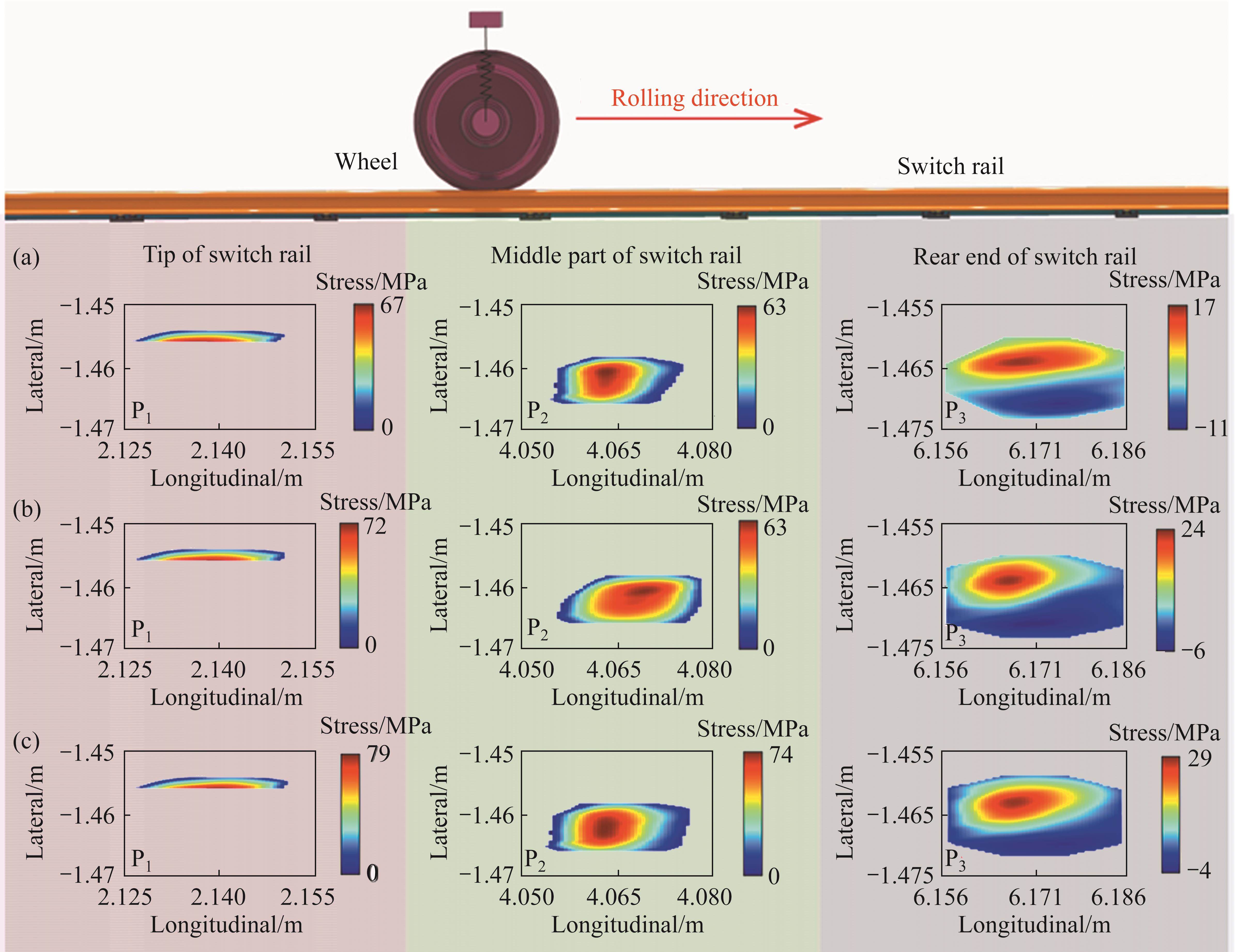
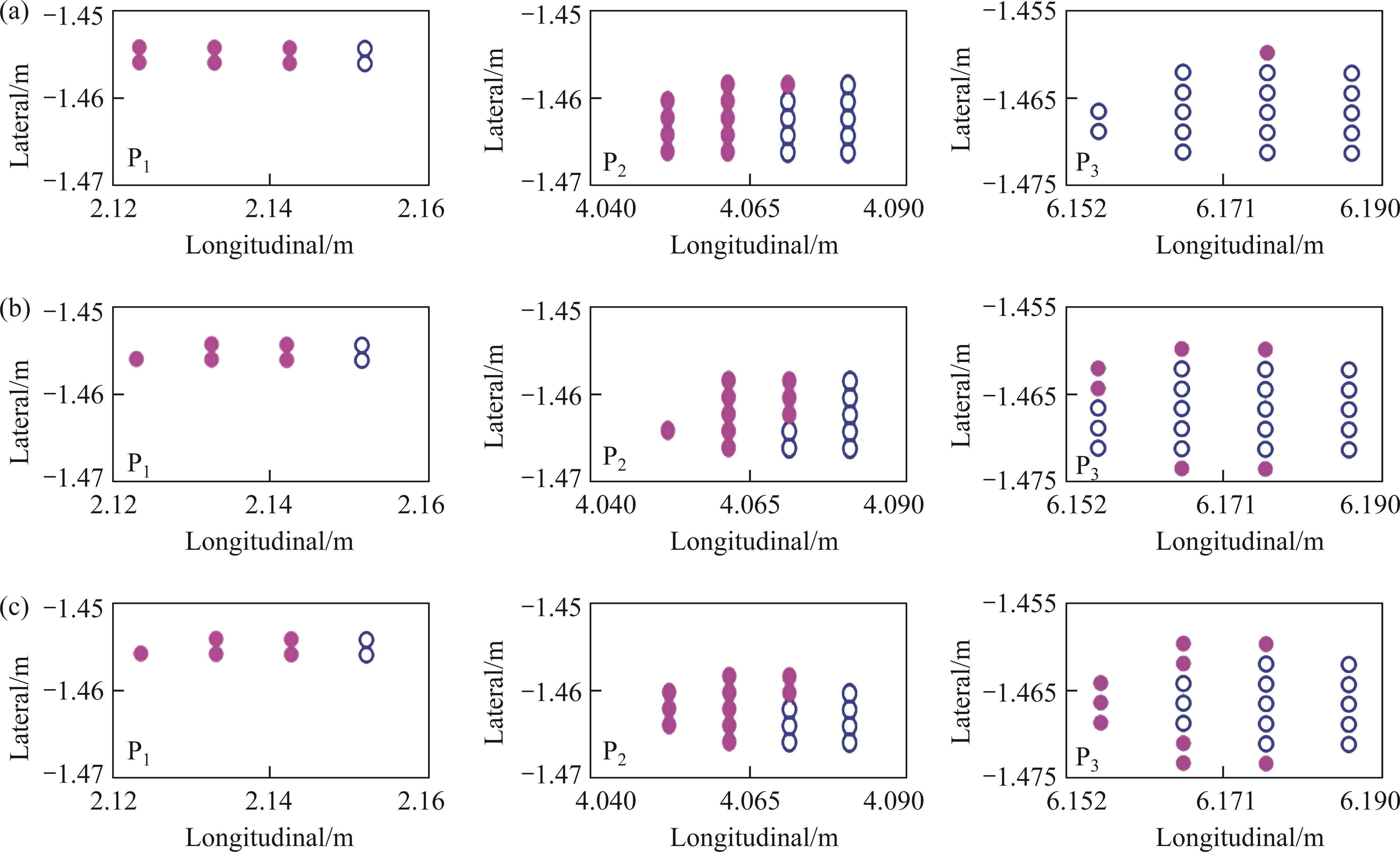
In Figure 6, we have selected three pivotal positions for in-depth examination of the wheel-rail contact states at these locations: P1, representing the initial phase of wheel load transition; P2, signifying the point of the maximum longitudinal stress; and P3, denoting the termination of the wheel-rail transition. In Figure 7, we depict the nodal contact stresses on the switch rail at these three designated positions under varying ramps. It is discernible from the figure that at position P1, the contact area is narrow. Although, at this juncture, the wheel-rail contact force has not yet reached its zenith, it manifests irregular contact characteristics, resulting in higher contact stress levels compared to position P2. Notably, considering that P1 corresponds to a weakened section of the switch rail, it may be more susceptible to damage. As we progress towards positions P2 and P3, the wheel-rail contact conditions gradually shift from irregular contact to conventional elliptical contact, thereby mitigating stress concentration phenomena. However, with the increment in ramps, the nodal longitudinal stress at all three positions escalates, with the increment ranging between 15% and 34%. Moreover, it is worth noting that the impact of ramps on the longitudinal interaction between the wheel and rail becomes more pronounced as one approaches the rear end of the switch rail.
To achieve a more comprehensive understanding of the wheel-rail contact state throughout the entire wheel load transfer process and its impact on rail damage, we present in Figure 8 the stick-slip distributions within the contact area at three distinct positions. The analysis reveals that at positions P1 and P2, the wheel-rail contact state is primarily characterized by slip, accounting for approximately 75% and 53% of the contact area, respectively. Consequently, throughout the entire wheel load transmission process, the interaction between the wheel and the switch rail is predominantly governed by slip, which exerts an adverse influence on switch rail wear and rolling contact fatigue. At position P3, the proportion of the slip region within the contact patch progressively increases with the increase in ramp, shifting from nearly 0% (0‰ ramp) to approximately 40% (40‰ ramp). This observation implies that as the ramp increases, the share of the slip zone in the wheel-rail contact area expands, potentially exacerbating the progression of switch rail damage. Notably, this phenomenon becomes more pronounced towards the rear end of the switch rail.
4 Discussion
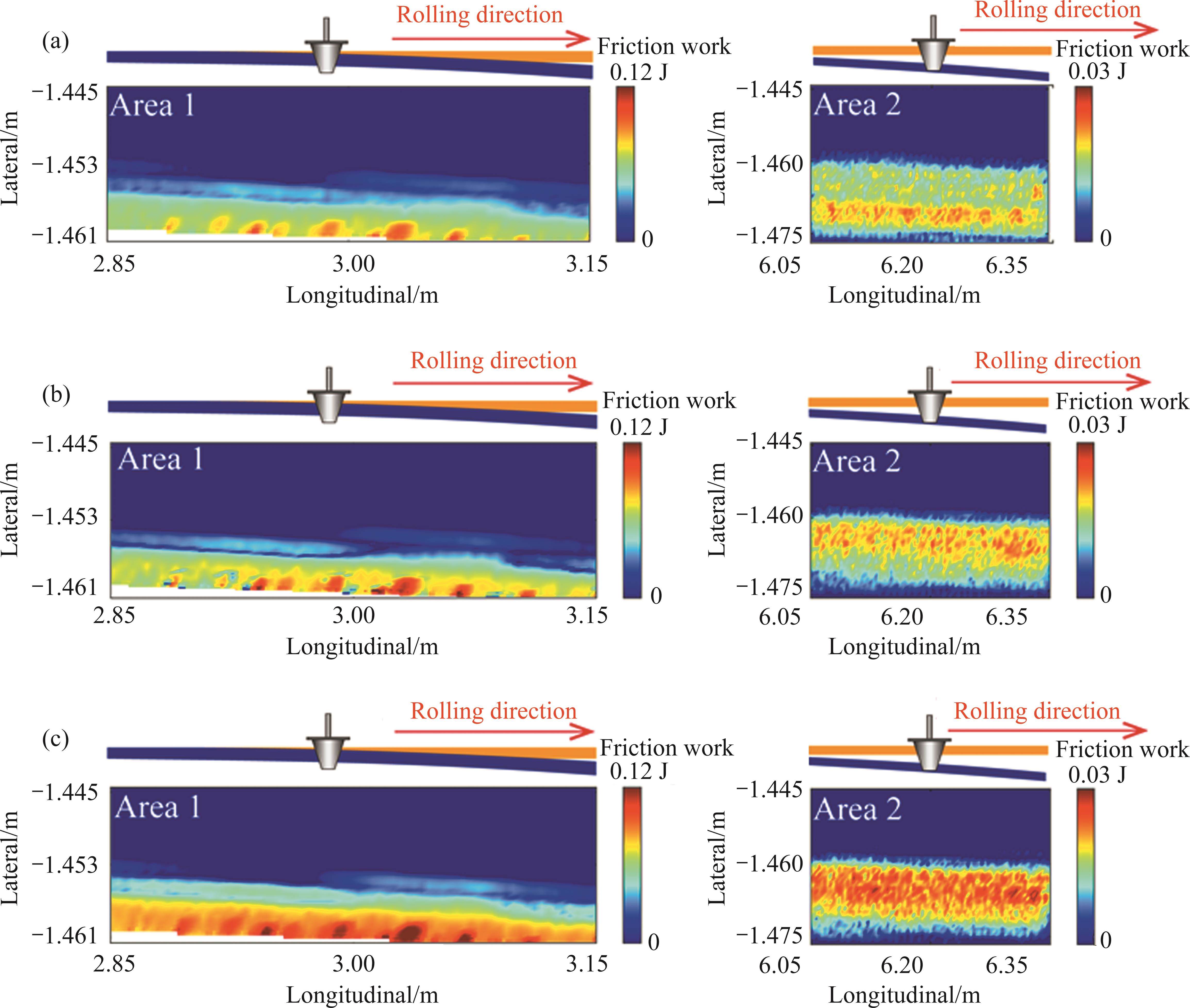
To delve further into the influence of these mechanical characteristics on switch rail wear and damage, this chapter involves the computation of friction work and damage factors for the switch rail surface under varying ramp conditions. Notably, friction work is closely associated with rail wear and is a widely accepted metric for quantifying rail surface wear [25, 26]. The calculation of friction work at a specific point on the switch rail surface is performed using Eq. (2) [25, 27, 28]:

where τ and s represent the surface shear stress and longitudinal slip at a given node, while τi and si denote the shear stress and longitudinal slip at the node at time i, respectively. The variables 
In addition to wear, rolling contact fatigue is another key aspect of our investigation. This is due to the fact that during this phase, wheel-switch rail contact is irregular, and the cross-sectional integrity of the switch rail is compromised. In this study, we employ the Smith-Watson-Topper (SWT) parameter to assess rolling contact fatigue damage on the rail surface and identify critical planes where cracks may initiate [29, 30]. For a given material, SWT at a specific location can be computed using Eq. (3) [28]:

Here, σmax represents the maximum normal stress in a given direction, and Δε denotes the difference between the maximum and minimum normal stresses throughout the entire wheel-rail contact cycle. Notably, both σmax and Δε are functions of the angle of orientation. Consequently, SWT values are determined for all angles, with the maximum value denoted as SWTmax. The direction corresponding to SWTmax identifies the most severe damage direction, and its normal orientation designates the plane where cracks are most likely to initiate at that location. This critical plane is illustrated in Figure 10, where calculations were performed for the rail head of the pointed rail at Area 3 in Figure 6, and SWTmax values for different segments along the longitudinal axis of the rail, along with their corresponding critical planes, are plotted on the same coordinate system.
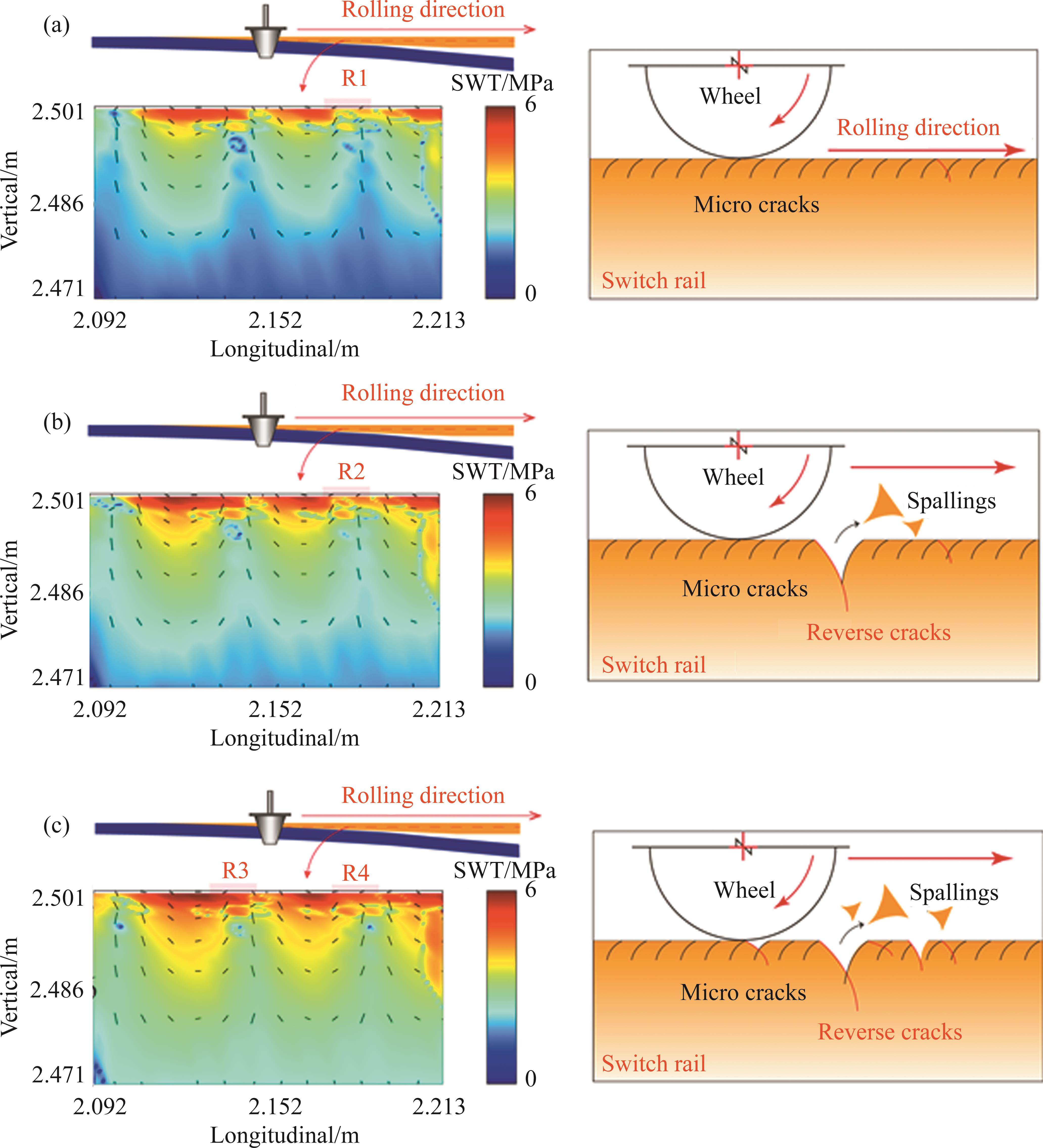
In Figure 10, the distribution of SWTmax and the critical plane are depicted on the left, while a schematic representation of the damage type is presented on the right. As observed in Figure 10(a), the maximum value of the switch rail damage factor, SWTmax, measures approximately 5.41 MPa, primarily concentrated within a depth of 4.6 mm beneath the rail’s top surface. Notably, owing to the vibration of the switch rail, rolling contact fatigue damage at the upper section of the switch rail exhibits non-uniform distribution along the rail’s longitudinal axis. In terms of potential crack initiation, most cracks align at an angle of approximately 135° relative to the direction of wheel travel, with a few positions (R1) exhibiting cracks at angles ranging from 35° to 45°. This damage pattern is illustrated in Figure 10(a), where damage on the upper surface of the switch rail is predominantly characterized by uniformly distributed oblique cracks.
When the rail ramp reaches 20‰, there is no discernible alteration in the distribution pattern of the SWTmax damage factor, as shown in Figure 10(b). However, the value increases by 5%, potentially leading to the gradual expansion of oblique cracks along the critical plane’s direction. At this juncture, specifically at position R2, the cracks continue to enlarge until they intersect in both forward and backward directions. This phenomenon may induce material spalling, resulting in spalling craters on the top surface of the switch rail, as depicted in Figure 10(b).
Upon reaching a rail ramp of 40‰ (representing a large ramp condition), SWTmax registers a 13.2% increase compared to the flat gradient condition. Simultaneously, the number of reverse cracks and their respective distribution areas experience a notable augmentation, with reverse cracks also appearing in the R3 region where SWTmax is higher, as depicted in Figure 10(c). This exacerbation may intensify top-surface spalling of the switch rail, thereby adversely affecting rolling contact fatigue damage on the rail.
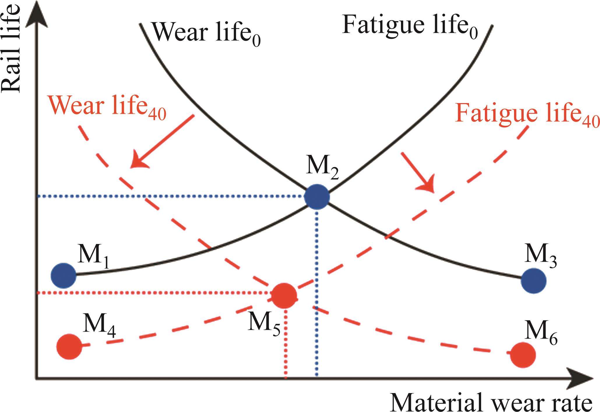
From the preceding study, it is evident that the impact of large ramps on rail damage is multifaceted. On one hand, these large ramps intensify rail wear rates, potentially expediting the onset and progression of surface wave wear. Conversely, they also exacerbate rolling contact fatigue damage and alter crack propagation, resulting in spalling. A schematic illustrating the influence of large ramps on rail damage is presented in Figure 11. Here, the black lines depict wear life and fatigue life curves for a zero incline. When abrasion rates are minimal, rail life is governed by rolling contact fatigue damage, as depicted by curves M1 and M2 in the figure. However, under high wear conditions, rail life is dictated by wear, illustrated by curves M2 and M3. Introducing a turnout on a large ramp accelerates rail wear, precipitating the development of corrugation and reducing wear life, as indicated by the transition from Wear life0 to Wear life40. Simultaneously, the fatigue life curve shifts from Fatigue life0 to Fatigue life40. Consequently, the overall life curve transforms to M4 to M5 to M6, resulting in a decline in the overall life of the turnout.
Based on the aforementioned calculation results, it becomes evident that the track ramp exerts minimal impact on the wear experienced at the front end of the switch rail during wheel load transfer. However, it significantly amplifies wear at the rear end of the switch rail. Concurrently, the interplay of slip contact during wheel load transfer and the vibration of the switch rail gives rise to conspicuous non-uniform wear patterns at the front end of the switch rail. This phenomenon may constitute a pivotal factor contributing to switch rail corrugation. Furthermore, the presence of a track ramp intensifies rolling contact fatigue damage at the front end of the switch rail during wheel load transition. This augmentation may lead to the emergence of cracks at angles less than 90° relative to the direction of movement. Under the influence of high-intensity wheel loads, these cracks may intersect, potentially resulting in surface spalling of the rail surface.
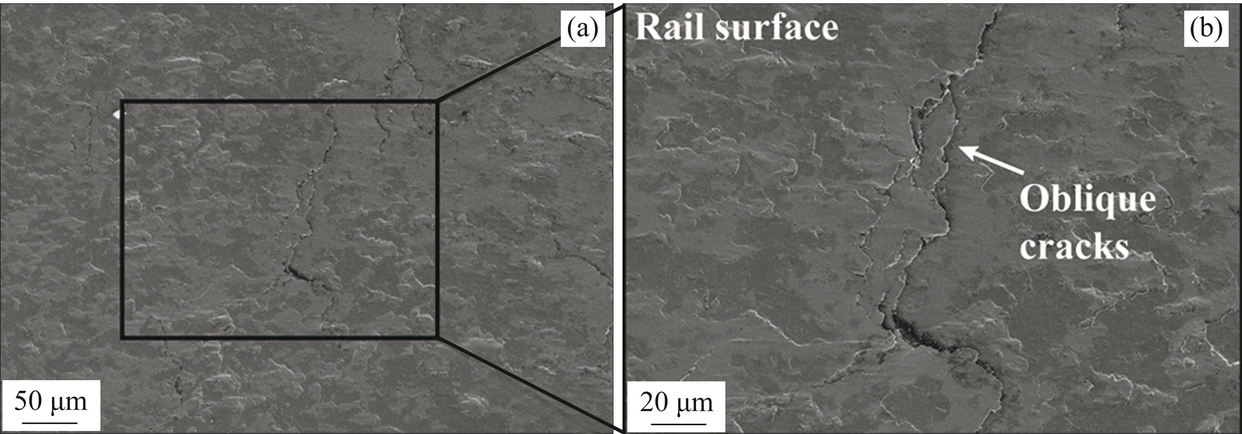
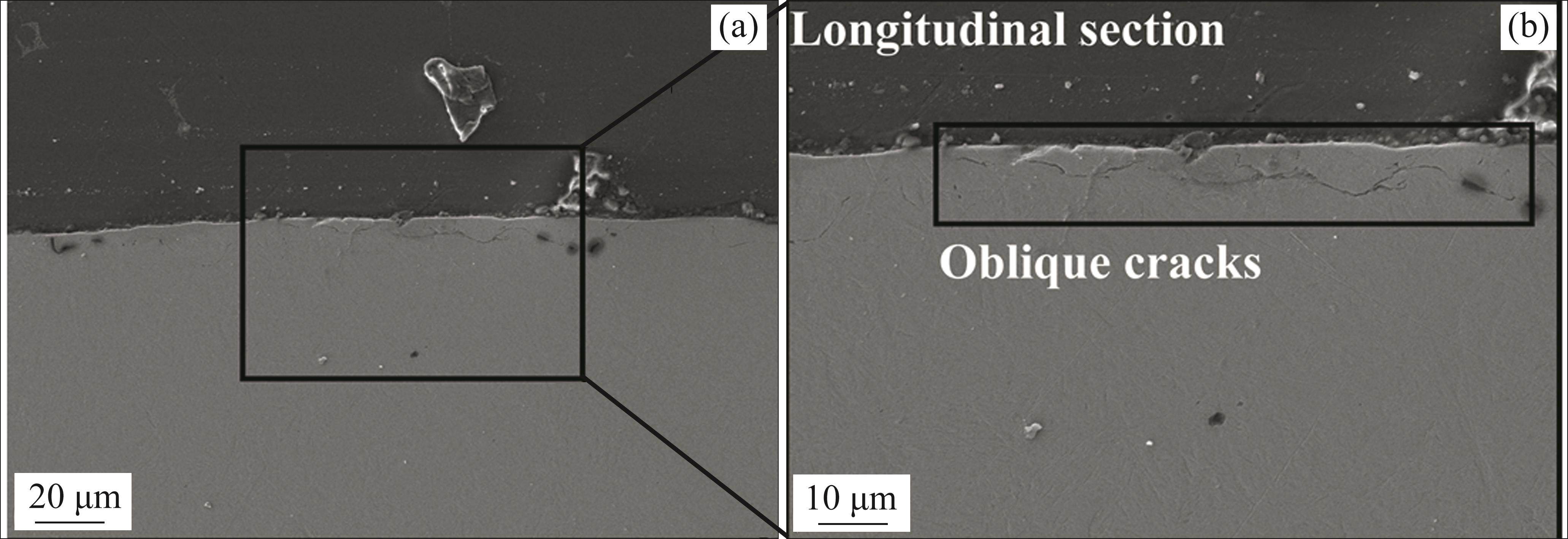
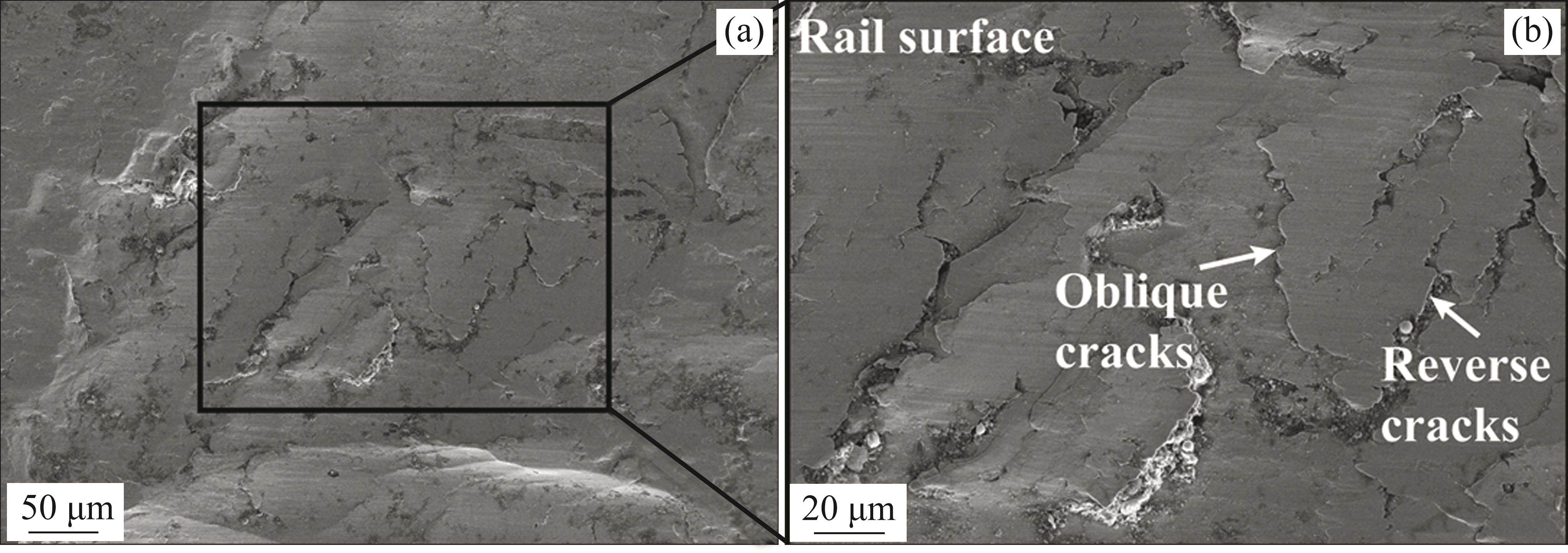
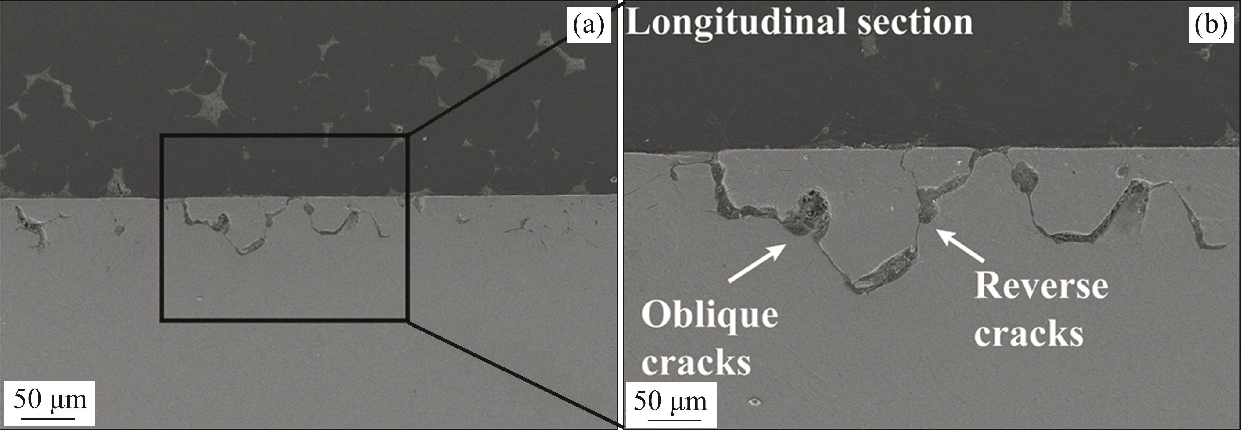
This phenomenon aligns with our field observations. In Figures 12 and 13, we present photographic documentation of rail surface and longitudinal section damage under flat ramp conditions, respectively. The illustrations reveal that the cracks on the rail surface predominantly propagate inward at a shallower angle, resulting in laminar spalling on the rail surface. In Figures 14 and 15, we display rail surface and longitudinal section damage photographs under a 25‰ ramp condition, respectively. In comparison to the rail damage observed under flat ramp conditions, there is a substantial increase in rail surface spalling, accompanied by a significant presence of reverse cracks. The intersection between reverse cracks and inclined cracks leads to material spalling on the rail surface. Moreover, the angle of these cracks undergoes a significant increase, rendering them more prone to penetrating the depth of the rail.
5 Conclusions
In this study, we have utilized the ANSYS/LS-DYNA explicit finite element method to construct a transient rolling contact finite element model of the wheel-rail system within a high-speed switch area, subject to varying ramp conditions. We have analyzed the mechanical response characteristics of the wheel-rail contact during the process of wheel load transfer, as the load transitions from the stock rail to the switch rail. Additionally, we have examined the influence of the switch rail ramp on wheel-rail contact properties, wear patterns, and rolling contact damage. Our key findings are summarized as follows:
1) During the wheel load transfer process, the vibration and incomplete constraint of the switch rail lead to periodic variations in the wheel-rail contact force on the switch rail. Notably, the track ramp has minimal impact on this periodic behavior. However, it exacerbates the longitudinal interactions between the wheel and rail, with the wheel-rail longitudinal force increasing by 35% under a 40‰ ramp compared to a flat ramp condition.
2) The wheel-rail contact state at the front end of the switch rail is primarily characterized by creep-slip interactions, while at the rear end, it is predominantly stick-slip based. The presence of a ramp amplifies the proportion of the contact area occupied by the slip zone, escalating from nearly 0% (0‰ ramp) to nearly 40% (40‰ ramp).
3) Significant discrepancies are observed in wear between the front and rear ends of the switch rail. Moreover, uneven wear patterns are notably evident, potentially serving as a crucial factor contributing to switch rail corrugation. Importantly, the track ramp does not alter this observed pattern but intensifies wear rate.
4) The track ramp exacerbates rail damage in the front wheel load transition area of the switch rail. Specifically, under 40‰ ramp conditions, the damage factor increases by 13.2% compared to flat ramp conditions. Simultaneously, it alters the direction of crack initiation, potentially leading to surface spalling of the rail.
These findings collectively provide valuable insights into the complex interplay of wheel-rail dynamics, switch rail damage, and ramp conditions, shedding light on critical aspects of rail system performance and maintenance.
Uniaxial and non-proportionally multiaxial ratcheting of U71Mn rail steel: Experiments and simulations
[J]. Mechanics of Materials, 2002, 34(12): 809-820. DOI: 10.1016/S0167-6636(02)00198-9.A full explicit finite element simulation for the study of interaction between wheelset and switch panel
[J]. Vehicle System Dynamics, 2020, 58(2): 229-248. DOI: 10.1080/0042311 4.2019.1575425.Stiffness characteristics of high-speed railway turnout and the effect on the dynamic train-turnout interaction
[J]. Shock and Vibration, 2016, 2016(1): 1258681. DOI: 10.1155/2016/125 8681.Observed failures at railway turnouts: Failure analysis, possible causes and links to current and future research
[J]. Engineering Failure Analysis, 2021, 119: 104987. DOI: 10.1016/j.engfailanal.2020.104987.Long-term rail profile damage in a railway crossing: Field measurements and numerical simulations
[J]. Wear, 2021, 472: 203331. DOI: 10.1016/j.wear.2020.203331.Influence of the motion conditions of wheelsets on dynamic derailment behaviour of a bogie in railway turnouts
[J]. Vehicle System Dynamics, 2022, 60(11): 3720-3742. DOI: 10.1080/00423114.2021.1975040.Investigation on train dynamic derailment in railway turnouts caused by track failure
[J]. Engineering Failure Analysis, 2022, 134: 106050. DOI: 10.1016/j.engfailanal.2022.106050.Assessment of non-Hertzian wheel-rail contact models for numerical simulation of rail damages in switch panel of railway turnout
[J]. Wear, 2019, 432: 102912. DOI: 10.1016/j.wear.2019.05.027.Simulation of wheel-rail contact and damage in switches & crossings
[J]. Wear, 2011, 271(1, 2): 472-481. DOI: 10.1016/j.wear.2010. 10.014.Study on rail corrugation on curved tracks on metro ramps
[J]. Wear, 2023, 523: 204769. DOI: 10.1016/j.wear.2023.204769.Investigation into the braking performance of high-speed trains in the complex braking environment of the Sichuan-Tibet Railway
[J]. Proceedings of the Institution of Mechanical Engineers, Part F: Journal of Rail and Rapid Transit, 2022, 236(7): 766-782. DOI: 10.1177/0954409721 1041884.Vehicle-track dynamics on a ramp and on the bridge: Simulation and measurements
[J]. Vehicle System Dynamics, 1999, 33(sup1): 604-615. DOI: 10.1080/00423114.1999.12063115.Experimental investigation of adhesion coefficient of wheel/rail under the track ramp conditions
[J]. Proceedings of the Institution of Mechanical Engineers, Part J: Journal of Engineering Tribology, 2014, 228(7): 808-815. DOI: 10.1177/13506501 14526386.Slip of wheels on rails: The root cause for rail undulant wear
[J]. Wear, 2023, 523: 204727. DOI: 10.1016/j.wear.2023.204727.Influence of the operational conditions on static and dynamic stiffness of rail pads
[J]. Mechanics of Materials, 2020, 148: 103505. DOI: 10.1016/j.mechmat.2020.103505.Numerical modeling of wheel-rail squeal-exciting contact
[J]. International Journal of Mechanical Sciences, 2019, 153: 490-499. DOI: 10.1016/j.ijmecsci.2019.02.012.A study on dynamic stress intensity factors of rail cracks at high speeds by a 3D explicit finite element model of rolling contact
[J]. Wear, 2016, 366: 60-70. DOI: 10.1016/j.wear.2016.06.001.Numerical modeling of dynamic frictional rolling contact with an explicit finite element method
[J]. Tribology International, 2019, 129: 214-231. DOI: 10.1016/j.triboint.2018.08.028.Influence of unilateral low adhesion on transient wheel-rail rolling contact and wheel damages
[J]. Wear, 2023, 530: 205053. DOI: 10.1016/j.wear.2023.205053.On the coupling of the vertical, lateral and longitudinal wheel-rail interactions at high frequencies and the resulting irregular wear
[J]. Wear, 2019, 430: 317-326. DOI: 10.1016/j.wear.2019.05.017.Modelling of non-steady-state transition from single-point to two-point rolling contact
[J]. Tribology International, 2016, 101: 152-163. DOI: 10.1016/j.triboint.2016.04.023.Local rolling contact fatigue and indentations on high-speed railway wheels: Observations and numerical simulations
[J]. International Journal of Fatigue, 2017, 103: 5-16. DOI: 10. 1016/j.ijfatigue.2017.05.014.An investigation into transient frictional rolling contact behaviour in a switch panel: Validation and numerical simulation
[J]. Vehicle System Dynamics, 2022, 60(1): 114-131. DOI: 10.1080/00423114.2020.1802492.A review of loading conditions for railway track structures due to train and track vertical interaction
[J]. Structural Control and Health Monitoring, 2008, 15(2): 207-234. DOI: 10.1002/stc.227.Modeling of high-speed wheel-rail rolling contact on a corrugated rail and corrugation development
[J]. Journal of Zhejiang University Science A, 2014, 15: 946-963. DOI: 10.1631/jzus.a1400191.Parameters studies for rail wear in high-speed railway turnouts by unreplicated saturated factorial design
[J]. Journal of Central South University, 2017, 24(4): 988-1001. DOI: 10.1007/s11771-017-3501-1.Multiscale analysis of wheel-rail rolling contact wear and damage mechanisms using molecular dynamics and explicit finite elements
[J]. Tribology International, 2023, 185: 108574. DOI: 10.1016/j.triboint.2023.108574.Effect of material non-uniformity and residual stress on wear and transient rolling contact behaviour in laminar plasma quenched (LPQ) rails
[J]. Wear, 2023, 523: 204767. DOI: 10.1016/j.wear.2023.204767.Failure analysis study of railway draw-hook coupler
[J]. Journal of Central South University, 2019, 26(4): 916-924. DOI: 10.1007/s11771-019-4060-4.Numerical investigation on the rolling contact wear and fatigue of laser dispersed quenched U71Mn rail
[J]. International Journal of Fatigue, 2021, 143: 106010. DOI: 10.1016/j.ijfatigue.2020.106010.WANG Kai, ZHU Hui, XU Jing-mang, BAI Tao-shuo, TIAN Chun-xiang, QIAN Yao, GAO Yuan, CHEN Rong, WANG Ping, and LIU Ya-nan declare that they have no conflict of interest.
WANG Kai, ZHU Hui, XU Jing-mang, BAI Tao-shuo, TIAN Chun-xiang, QIAN Yao, GAO Yuan, CHEN Rong, WANG Ping, LIU Ya-nan. Study on the damage mechanism of high-speed turnout switch rails on large ramps [J]. Journal of Central South University, 2025, 32(1): 288-303. DOI: https://doi.org/10.1007/s11771-025-5858-x.
王凯,朱辉,徐井芒等.大坡道上高速道岔转辙器尖轨的损伤机制研究[J].中南大学学报(英文版),2025,32(1):288-303.

